
Modular switchgear connection and method of electrically connecting a modular compartment to a switchgear assembly

a modular compartment and switchgear technology, applied in the field of switchgears, can solve the problems of cumbersome removal and installation, and compound the challenges of removal and installation process

Active Publication Date: 2015-12-10
ABB (SCHWEIZ) AG
View PDF13 Cites 9 Cited by
  • Summary
  • Abstract
  • Description
  • Claims
  • Application Information

AI Technical Summary

Benefits of technology

This patent describes a connection system for modular switchgear that allows for easy and quick installation. The system includes a branch busbar, a connection arrangement with a fastener and a spout, and a contact component with a base and a cylindrical portion that receives the fastener. The system can be installed by aligning the spout with the fastener and then securing the contact component and the spout to the branch busbar using the nut. The technical effect of this system is that it simplifies the installation process and reduces installation time.

Problems solved by technology

Unfortunately, to establish an electrical connection between the busbar and the connectors of the compartment, the busbar is typically mounted at an interior region of the spout, such that removal and installation is cumbersome.
An additional challenge associated with removal and installation of the compartments relates to the location of the connectors.
The switchgear assemblies are often disposed against a wall, thereby compounding the removal and installation process challenges.

Method used


Image

  • Modular switchgear connection and method of electrically connecting a modular compartment to a switchgear assembly
  • Modular switchgear connection and method of electrically connecting a modular compartment to a switchgear assembly
  • Modular switchgear connection and method of electrically connecting a modular compartment to a switchgear assembly

Examples


Embodiment Construction

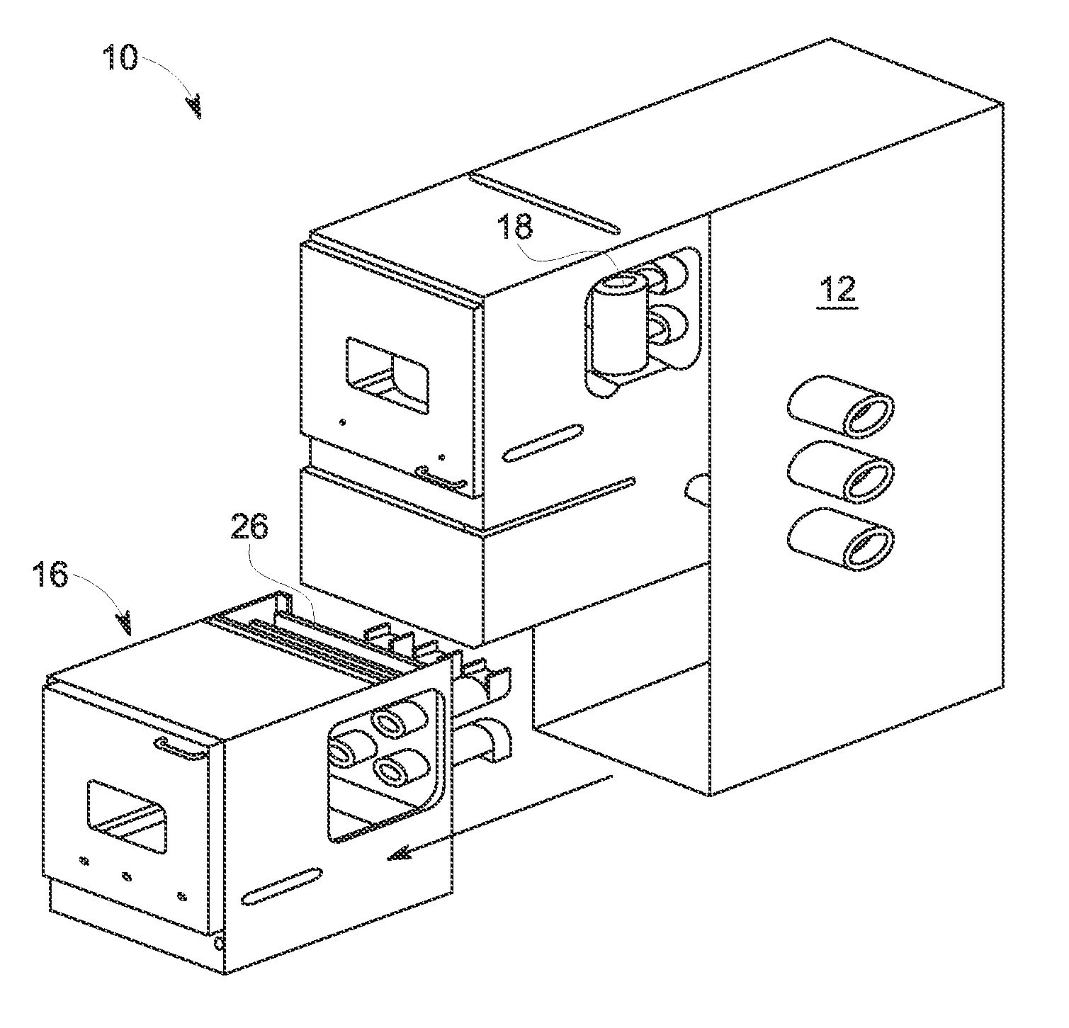
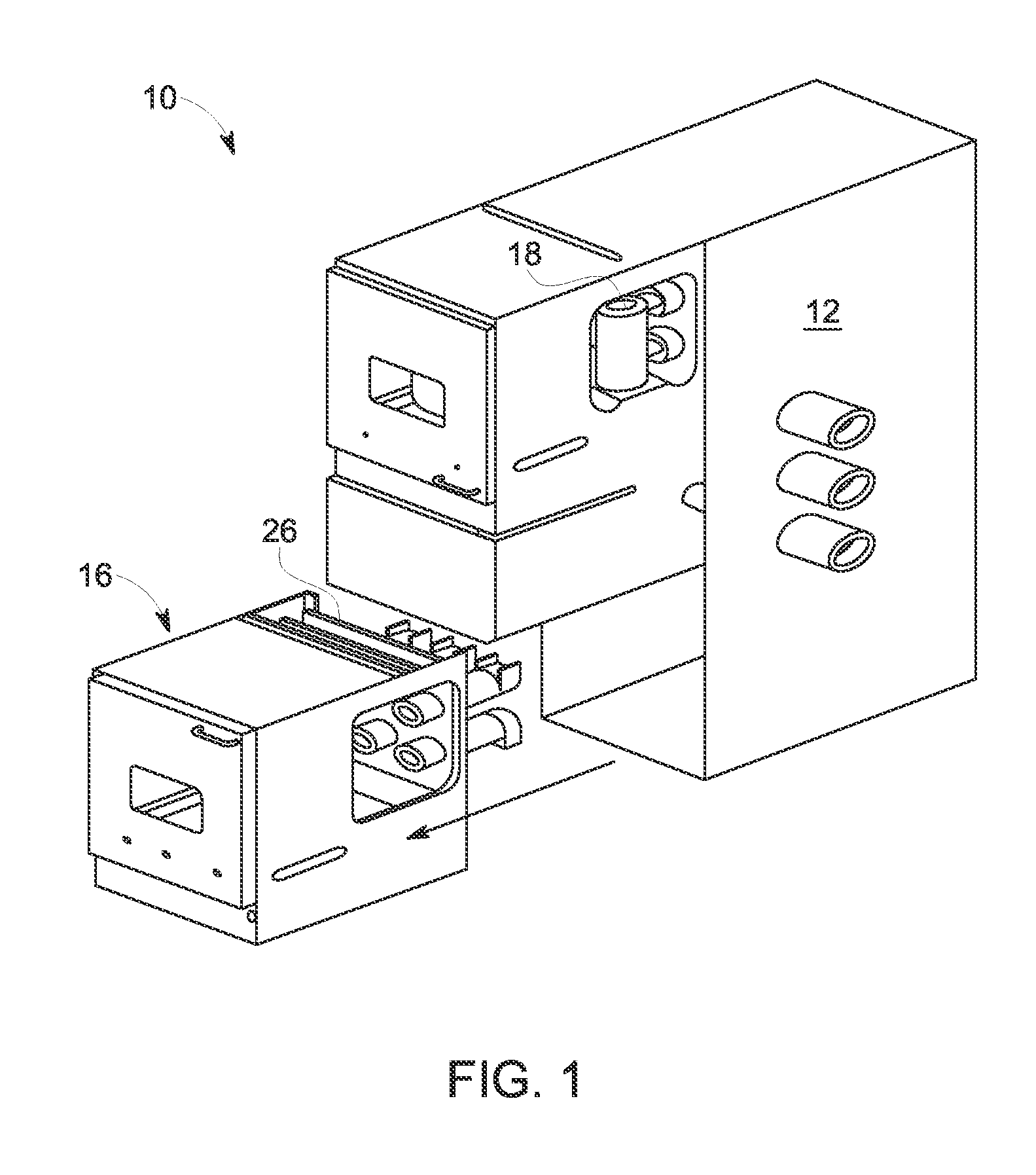
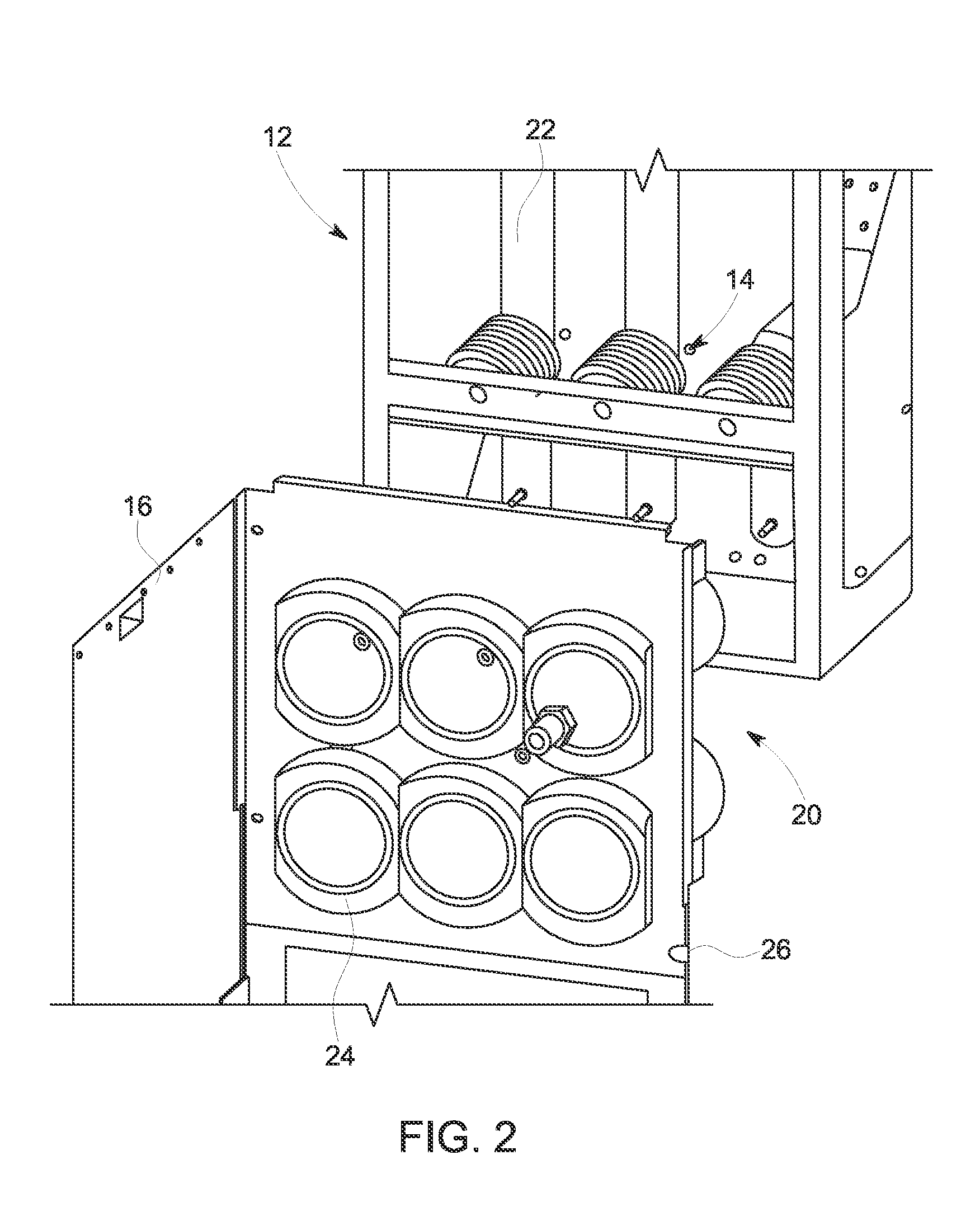
[0016]Referring to FIGS. 1 and 2, a switchgear assembly 10 is illustrated and includes a main busbar circuit portion 12 housing a plurality of electrical components 14 for routing power throughout the switchgear assembly 10. A modular compartment 16 is illustrated in a removed position from the remainder of the switchgear assembly 10 and, as shown, a plurality of compartments is typically included in the switchgear assembly 10. Some or all of the compartments may be of the modular configuration described herein. Each of the compartments, whether modular or not, segregate an electrical device 18 disposed in each compartment from one another, each of the electrical devices performing distinct functions from one another. The segregation improves reliability and overall safety of the switchgear assembly 10. Typical compartments include a low voltage compartment, a circuit breaker compartment, a main bus compartment and cable compartment, for example.

[0017]The modular compartment 16 prov...


PUM


Abstract

A modular switchgear electrical connection for use with a modular compartment includes a branch busbar having a busbar aperture defined by the branch busbar. Also included is a connection arrangement for establishing an electrical connection with the branch busbar. The connection arrangement includes a fastener extending through the busbar aperture toward the modular compartment. The connection arrangement also includes a spout including a base wall and a cavity defined by at least one wall extending from the base wall, wherein the base wall includes a spout aperture for receiving the fastener. The connection arrangement further includes a contact component including a base portion a cylindrical portion extending from the base portion, the contact component defining an aperture for receiving the fastener, the contact component secured to the spout and the fastener with a nut for engaging the fastener.

Description

BACKGROUND OF THE INVENTION[0001]The subject matter disclosed herein relates to switchgears, and more particularly to a modular switchgear connection, as well as a method of electrically connecting a modular compartment to a switchgear assembly.[0002]Switchgear assemblies typically include a plurality of compartments for housing a variety of electrical components that provide necessary functions for overall operation of the switchgear assembly. The various electrical components require an electrical connection to a main busbar circuit of the switchgear assembly, typically via one or more connectors located in a rear portion of the compartment that facilitates an electrical connection to a busbar. The connector(s) often include a spout that functions as an insulator / bushing system at the back of the compartment, which allows contact connections of the electrical component, such as a circuit breaker, for example, to be plugged into the busbar.[0003]The switchgear assemblies may requir...

Claims


Application Information

Patent Timeline
IPC IPC(8): H01R25/16H01R9/18H01R43/20
CPCH01R25/162Y10T29/4921H01R9/18H01R43/20H02B1/21H02B11/04H02B3/00
Inventor REN, XUHUI
Owner ABB (SCHWEIZ) AG
Learn More