

Method for a Current Mode Buck-Boost Converter
a current mode and converter technology, applied in the direction of dc-dc conversion, power conversion systems, instruments, etc., can solve problems such as serious challenges, and achieve the effect of reducing the switching loss of buck-boost converters
- Summary
- Abstract
- Description
- Claims
- Application Information
AI Technical Summary
Benefits of technology
Problems solved by technology
Method used
Image

Examples
Embodiment Construction
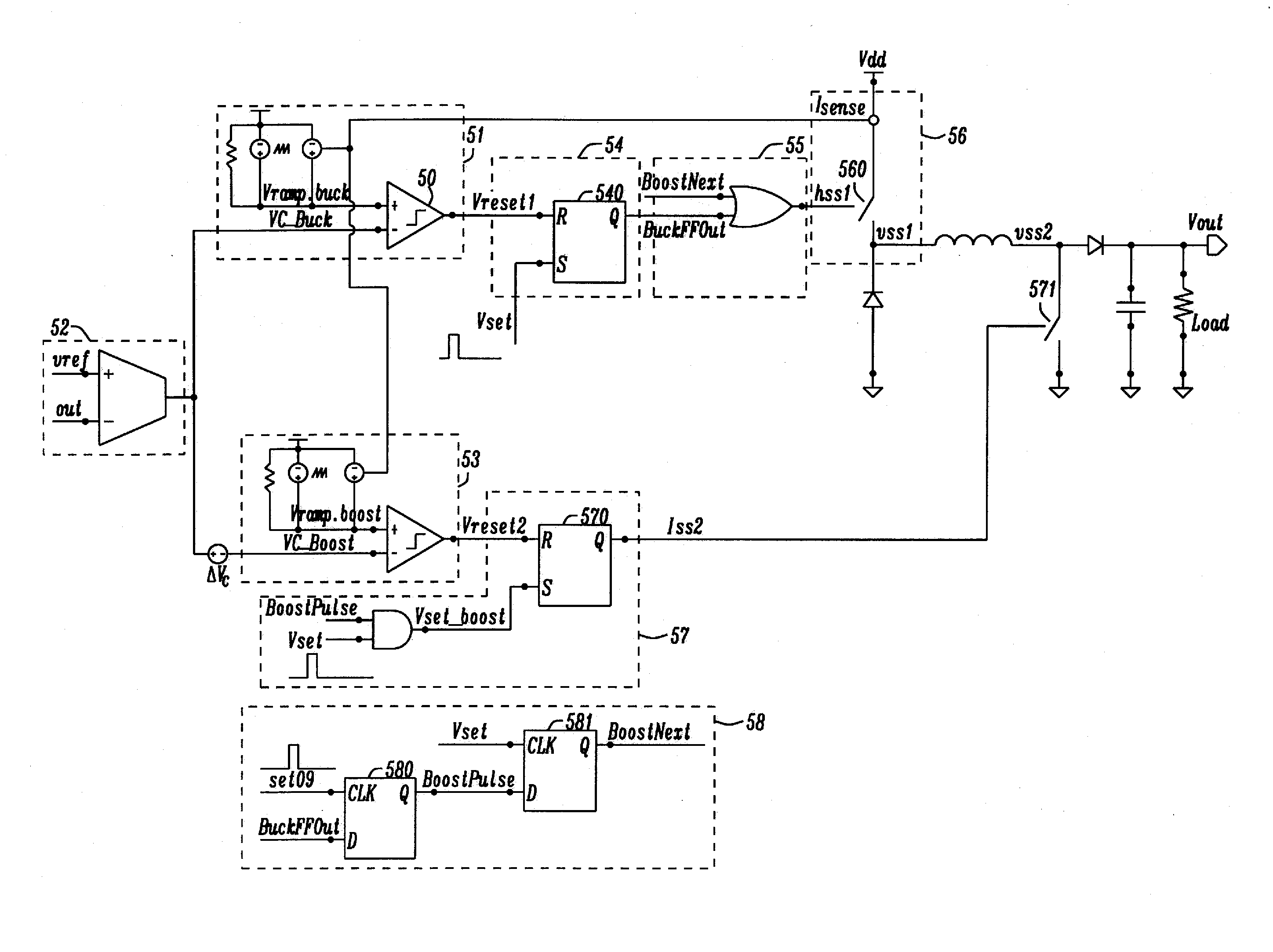
[0046]Methods and circuits are disclosed to achieve buck-boost converters with current mode control (CMC) and separated buck and boost pulses. If switching in buck mode and the buck duty cycle DBUCK is greater than a set reference duty cycle DSET, then in the next cycle boost mode switching will occur. Typical values for the reference duty cycle DSET may be between about 80 and 90%, depending on system requirements.
[0047]Furthermore if switching in boost mode and DBuckset, then in the next cycle Buck mode switching will occur. It is possible to track Buck comparator output and the related duty cycle, which is not in effect during Boost mode operation. Thus mode change decision will only be dependent on a single input DBuck.
[0048]Moreover the control loop of the buck-boost converters disclosed will incorporate a single loop filter and error amplifier, wherein control voltages for a buck comparator and a boost comparator will be related and defined with the following formula:
Vc,Buck=V...
PUM
 Abstract
Description
Claims
Application Information