

Method and device for controlling an inverter
- Summary
- Abstract
- Description
- Claims
- Application Information
AI Technical Summary
Benefits of technology
Problems solved by technology
Method used
Image

Examples
Embodiment Construction
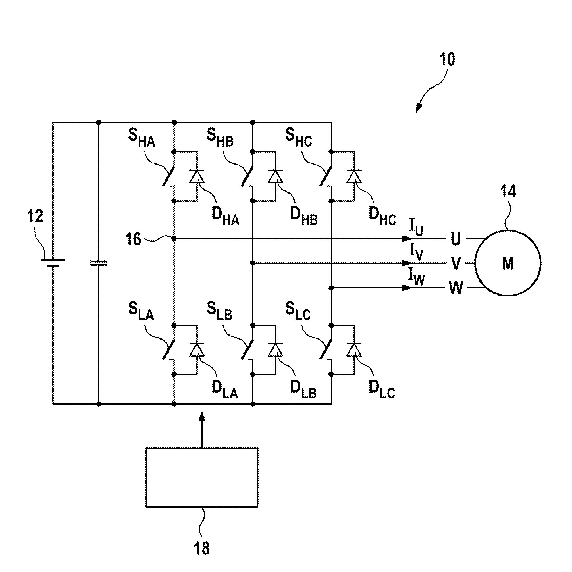
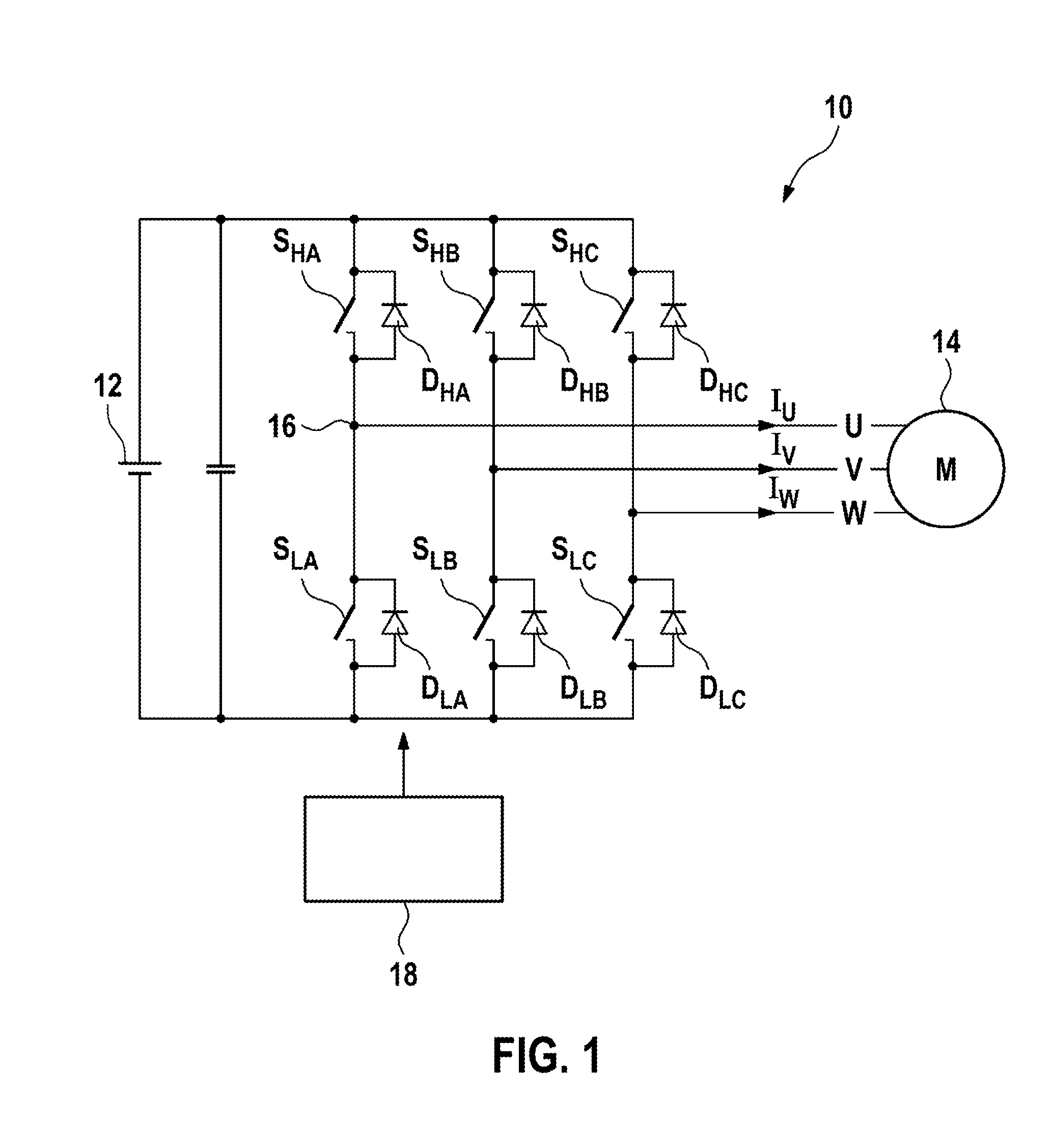
[0049]FIG. 1 schematically illustrates an inverter for controlling an electrical load, in particular an electrical machine, which inverter is generally denoted by 10.
[0050]The inverter 10 is connected to a DC voltage source 12 and is used to energize the electrical load 14, which in this case is designed as an electrical machine 14, in a three-phase fashion. The inverter has three half-bridges which are connected in parallel with the DC voltage source 12 and have in each case two controllable switches S. Between the switches S, a half-bridge tap 16 is formed in each case, which half-bridge taps are each connected to a phase conductor of the phases U, V, W of the electrical machine 14.
[0051]In each case, a freewheeling diode D which enables a flow of current in the opposite direction is connected in parallel with the switches S.
[0052]In FIG. 1, the switches S are denoted by SHA, SLA, SHB, SLB, SHC, SLC corresponding to the phase U, V, W which they provide and corresponding to the ass...
PUM
 Abstract
Description
Claims
Application Information