Optical Filter on Objective Lens for 3D Cameras

a technology of optical filter and objective lens, which is applied in the direction of camera filters, instruments, and reradiation, can solve the problems of image noise and may reach saturation, and achieve the effects of reducing the effective aoi, reducing and increasing the spectral width of the bandpass filter

Inactive Publication Date: 2015-12-10
HEPTAGON MICRO OPTICS
View PDF0 Cites 33 Cited by
  • Summary
  • Abstract
  • Description
  • Claims
  • Application Information

AI Technical Summary

Benefits of technology

[0010]A bigger AOI requires further increases in the spectral width of the bandpass filter. This allows as much of the light as possible of the active camera system to pass onto the sensor. At the same time, increased levels of background li

Problems solved by technology

The challenge of 3D time-of-flight (TOF) cameras is that a large spectral width of the bandpass filter has to be chosen in order to account for different widths, drifts and tolerances, including the emitter's bandwidth,

Method used


Image

  • Optical Filter on Objective Lens for 3D Cameras
  • Optical Filter on Objective Lens for 3D Cameras
  • Optical Filter on Objective Lens for 3D Cameras

Examples


Embodiment Construction

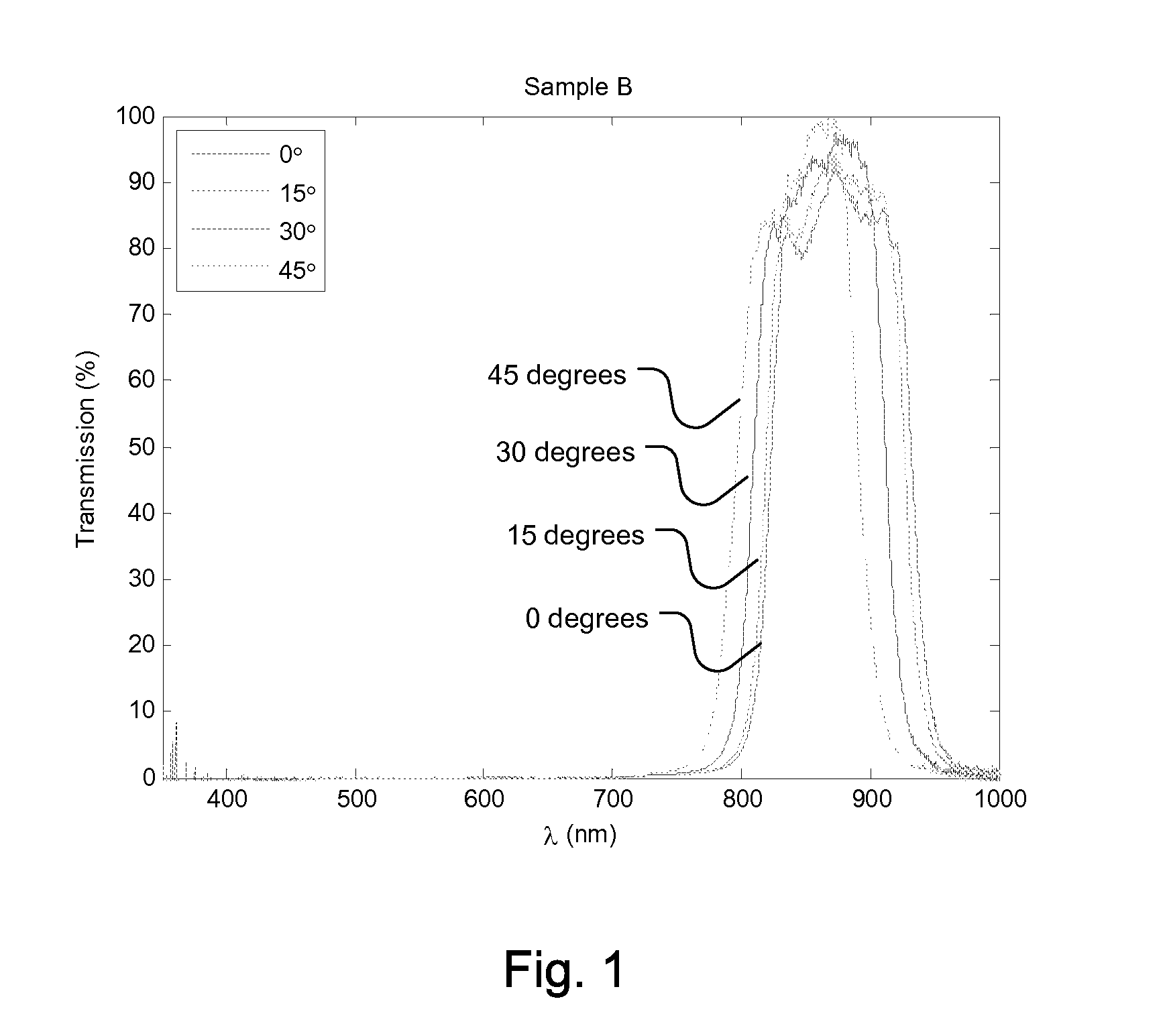
[0024]A drawback of state-of-the-art 3D time-of-flight (TOF) cameras is that a large spectral width of the bandpass filter must be chosen in order to account for several different factors, including the AOI. Increased AOIs are correlated with increased bandpass shifts towards shorter wavelengths.

[0025]This is illustrated by a plot of typical transmission curves of the optical bandpass filter as used in 3D TOF cameras shown in FIG. 1.

[0026]Here, percent transmission is plotted as a function of wavelength. Transmission curves for several different AOIs are shown. As the AOI is increased, a greater shift of the bandpass opening towards shorter wavelengths is observed. Therefore, a larger AOI requires an increase in the spectral width of the bandpass filter, resulting in increased levels of background light passing through the filter and an increasingly noisy image.

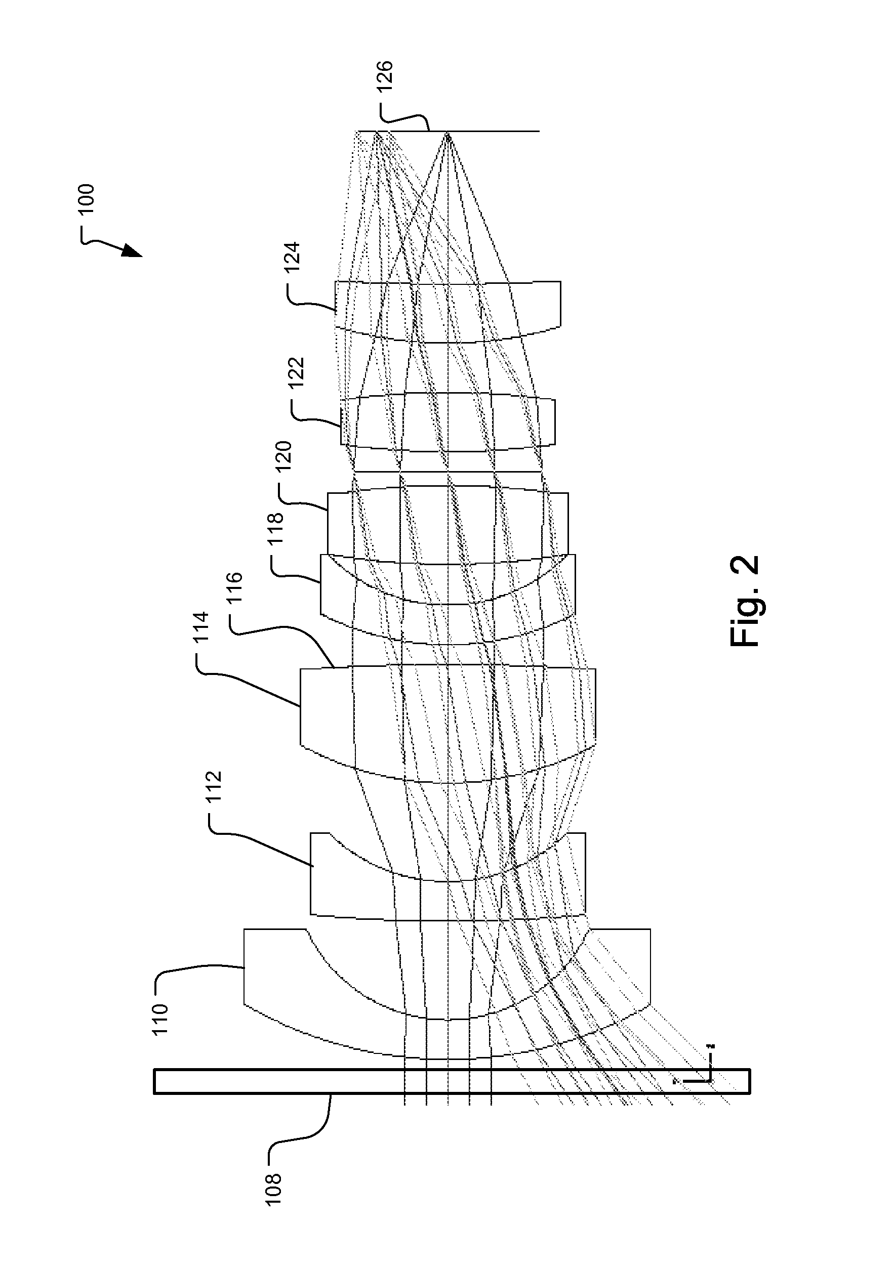
[0027]By applying the bandpass filter directly to one of the surfaces inside the objective lens system, preferably to the p...


PUM


Abstract

An optical bandpass filter for background light suppression in a three-dimensional time of flight camera is added on one of the lens surfaces inside the objective lens system.

Description

RELATED APPLICATIONS [0001]This application claims the benefit under 35 USC 119(e) of U.S. Provisional Application No. 61 / 289,475, filed on Dec. 23, 2009, which is incorporated herein by reference in its entirety.BACKGROUND OF THE INVENTION [0002]Three dimensional (3D) time-of-flight (TOF) cameras are active systems that include a light emitter that generates modulated light in a narrow spectral band. As a result, they do not require ambient or background light. In fact, for 3D TOF cameras, ambient light constitutes a noise source that may even cause sensor pixels to saturate.[0003]In order to suppress background light, all 3D time-of-flight cameras on the market use optical bandpass filters such that only light in the narrow spectral band of the light emitter can reach the TOF detector chip.[0004]Background light can originate from artificial light sources (mainly in indoor environment) or from the sun (in outdoor environments). Because of the large amount of background light prese...

Claims


Application Information

Patent Timeline
IPC IPC(8): H04N13/02G02B13/18G03B11/00G02B5/20G02B9/64
CPCH04N13/0203G02B13/18G03B11/00G02B9/64G02B13/04G01S7/4816G01S17/894
Inventor OGGIER, THIERRY
Owner HEPTAGON MICRO OPTICS
Why Eureka
Try Eureka