
Semiconductor laser light source and laser projector

A laser projector and laser light source technology, applied in the laser field, can solve the problems of affecting the life of the laser system, the method of eliminating speckle is complicated, etc., to achieve the effect of improving the picture quality, improving the viewing experience, and increasing the spectral width

Inactive Publication Date: 2020-03-27
SICHUAN CHANGHONG ELECTRIC CO LTD
View PDF5 Cites 3 Cited by
  • Summary
  • Abstract
  • Description
  • Claims
  • Application Information

AI Technical Summary

Problems solved by technology

[0004] The present invention aims to solve the problem that the existing speckle elimination method is complex and affects the life of the laser system, and proposes a semiconductor laser light source and a laser projector

Method used


Image

  • Semiconductor laser light source and laser projector
  • Semiconductor laser light source and laser projector
  • Semiconductor laser light source and laser projector

Examples


Embodiment 1

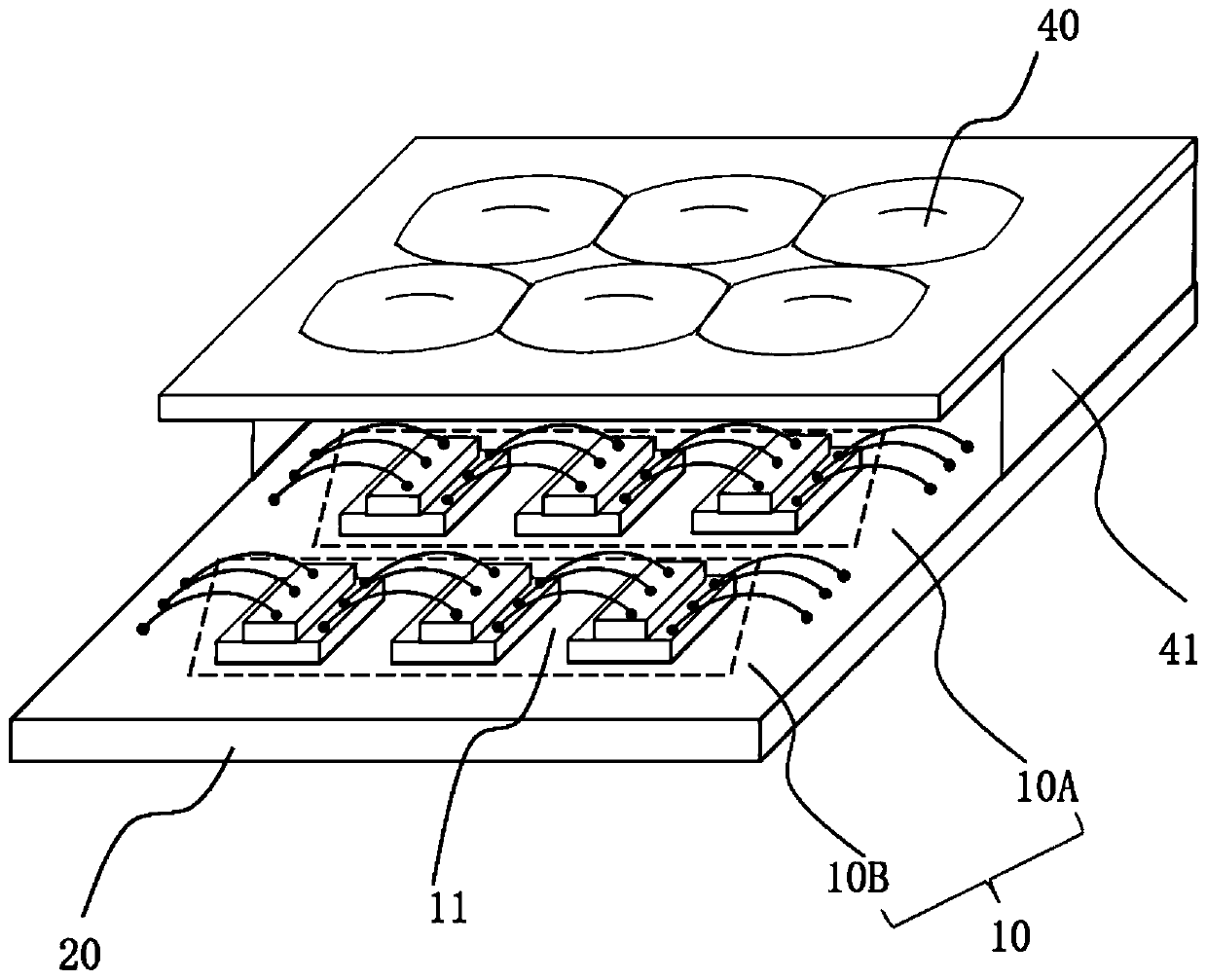
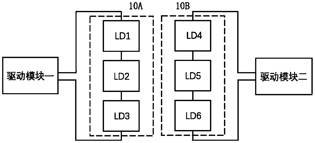
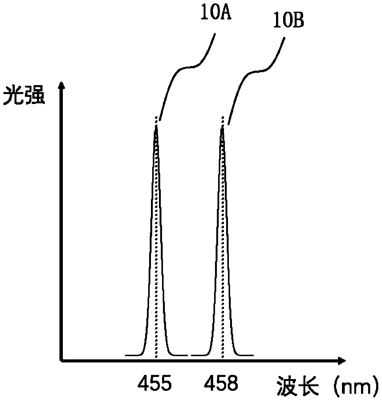
[0032] figure 1 Shown here is a schematic structural diagram of a semiconductor laser light source according to this embodiment, which includes a laser diode array 10, a substrate 20, a driving module 30, and a collimating module 40. The laser diode array 10 contains 6 laser diodes, each of which is divided into a laser diode group, which is distributed in a 2×3 rectangular array on the substrate 20 and is fixedly connected to the substrate 20. To avoid thermal interference between each other, the laser diodes are distributed at equal intervals of 5mm in two mutually perpendicular directions. The first row 10A of the laser diode array 10 is laser diode group one, including three laser diodes with the same center wavelength, and the second row 10B is laser diode group two, including three laser diode groups with the same center wavelength but the center of laser diode group one Laser diodes of different wavelengths. The substrate 20 may be made of alumina ceramic material with...

Embodiment 2

[0043] An embodiment of the present invention also provides a laser projector, which includes the semiconductor laser light source provided in Embodiment 1 of the present invention. Figure 4 Shown here is a schematic structural diagram of a laser projector described in this embodiment, which includes a semiconductor laser light source 100, a heat dissipation device 104, an opto-mechanical module 110, and a lens 120. The semiconductor laser light source 100 includes three semiconductor laser light sources, namely a first semiconductor laser light source 101, a second semiconductor laser light source 102 and a third semiconductor laser light source 103, which respectively output blue laser, green laser and red laser. The three semiconductor laser light sources are arranged on the heat sink 104 independently of each other. The heat dissipation device 104 may be a combination of a heat dissipation fan and a heat sink made of aluminum, copper or alloy materials, or may be other typ...


PUM

PropertyMeasurementUnit
wavelengthaaaaaaaaaa

Abstract

The invention relates to the technical field of laser, and aims to solve the problems that an existing speckle eliminating method is complex and influences the service life of a laser system. A semiconductor laser light source and a laser projector are provided. The semiconductor laser light source comprises a laser diode array and a driving module, the laser diode array comprises at least two laser diode groups with different central wavelengths. Each laser diode group comprises one or more laser diodes with the same central wavelength; the number of the driving modules is the same as that of the laser diode groups; the driving modules are connected with the corresponding laser diode groups; and the driving module is used for providing corresponding driving currents for the correspondinglaser diode groups, so that the difference value of the total light output power of any two laser diode groups in the laser diode array is within a preset range, and the total light output power is the sum of the light output power of all laser diodes in the laser diode groups. The method can effectively reduce speckle contrast.

Description

Technical field [0001] The present invention relates to the field of laser technology, in particular to a semiconductor laser light source and a laser projector. Background technique [0002] With the development of semiconductor laser technology, laser display technology (such as laser TV and laser cinema) using red, green, and blue lasers as light sources has become an important development direction for the next generation of display technology. Compared with traditional light emitting diode (LED) light sources, laser diode (LD) light sources have the following advantages: better monochromaticity, narrower spectral range, higher color saturation; three-color LD light sources cover a wider color gamut, The color reproduction is higher; the life of the light source is longer, up to more than 20,000 hours. [0003] Due to the strong coherence of the laser, a large number of irregularly distributed shiny spots will appear after scattering in a non-uniform medium or non-smooth surfa...

Claims


Application Information

Patent Timeline
Patent Type & Authority Applications(China)
IPC IPC(8): G03B21/20G02B27/48
CPCG02B27/48G03B21/2013G03B21/2033
Inventor 康健
Owner SICHUAN CHANGHONG ELECTRIC CO LTD
Learn More