Laser system with nonlinear compression

a nonlinear compression and laser system technology, applied in the field of laser systems, can solve the problems of severe subsurface damage, inability to subsurface compression of newly generated spectral portions by self-phase modulation, etc., and achieve the effect of simple and compact production

Inactive Publication Date: 2015-02-03
FRAUNHOFER GESELLSCHAFT ZUR FOERDERUNG DER ANGEWANDTEN FORSCHUNG EV +1
View PDF5 Cites 4 Cited by
  • Summary
  • Abstract
  • Description
  • Claims
  • Application Information

AI Technical Summary

Benefits of technology

[0007]Now, therefore, it is the object of the present invention to create a laser system which gener

Problems solved by technology

If several longitudinal modes with a statistical phase relationship contributed to the emission, a subsequent compression

Method used


Image

  • Laser system with nonlinear compression
  • Laser system with nonlinear compression
  • Laser system with nonlinear compression

Examples


Embodiment Construction

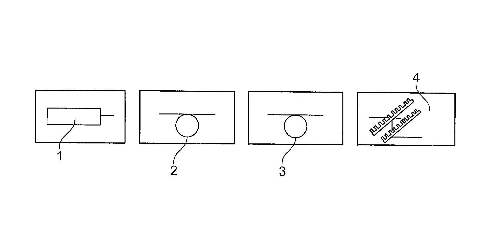
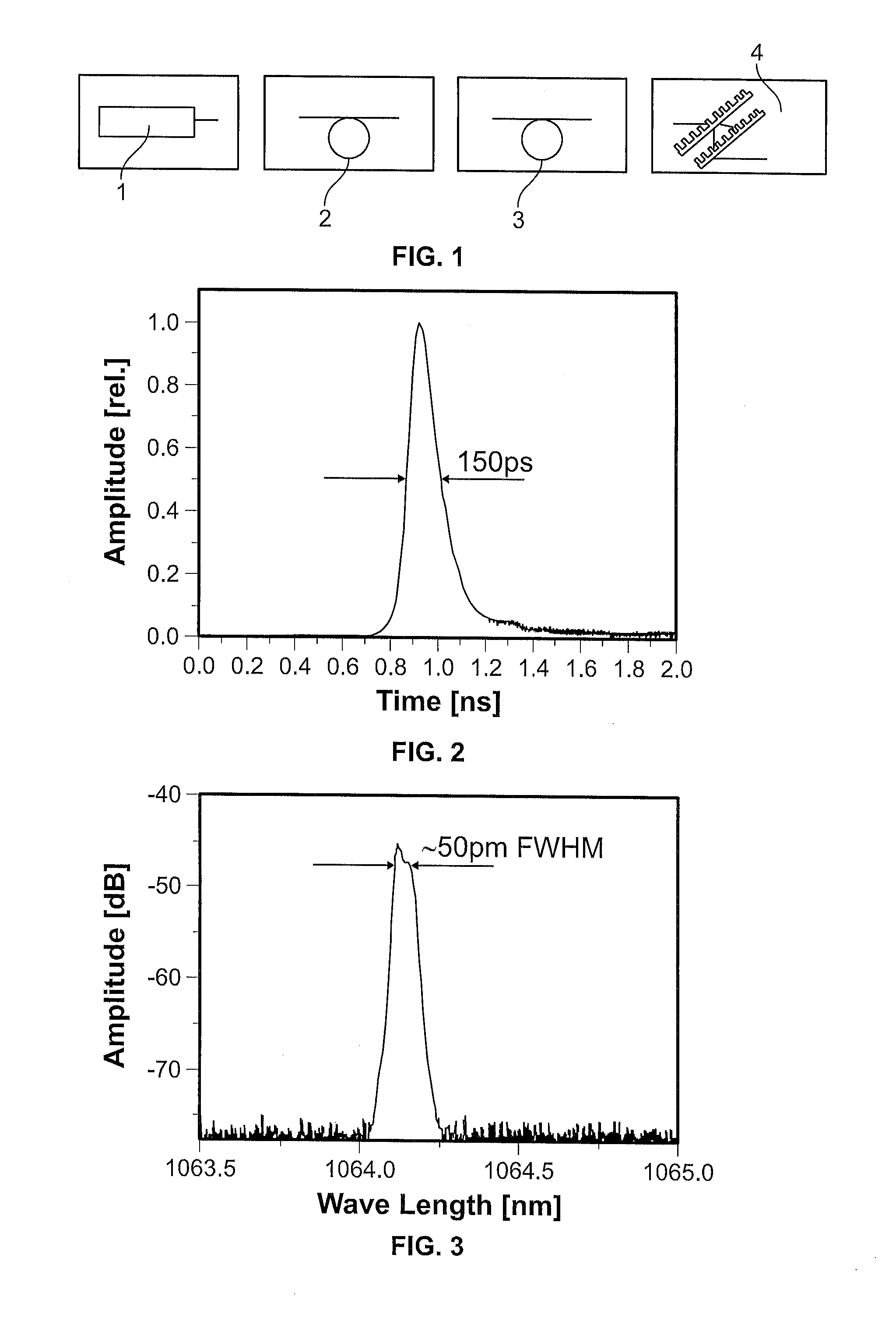
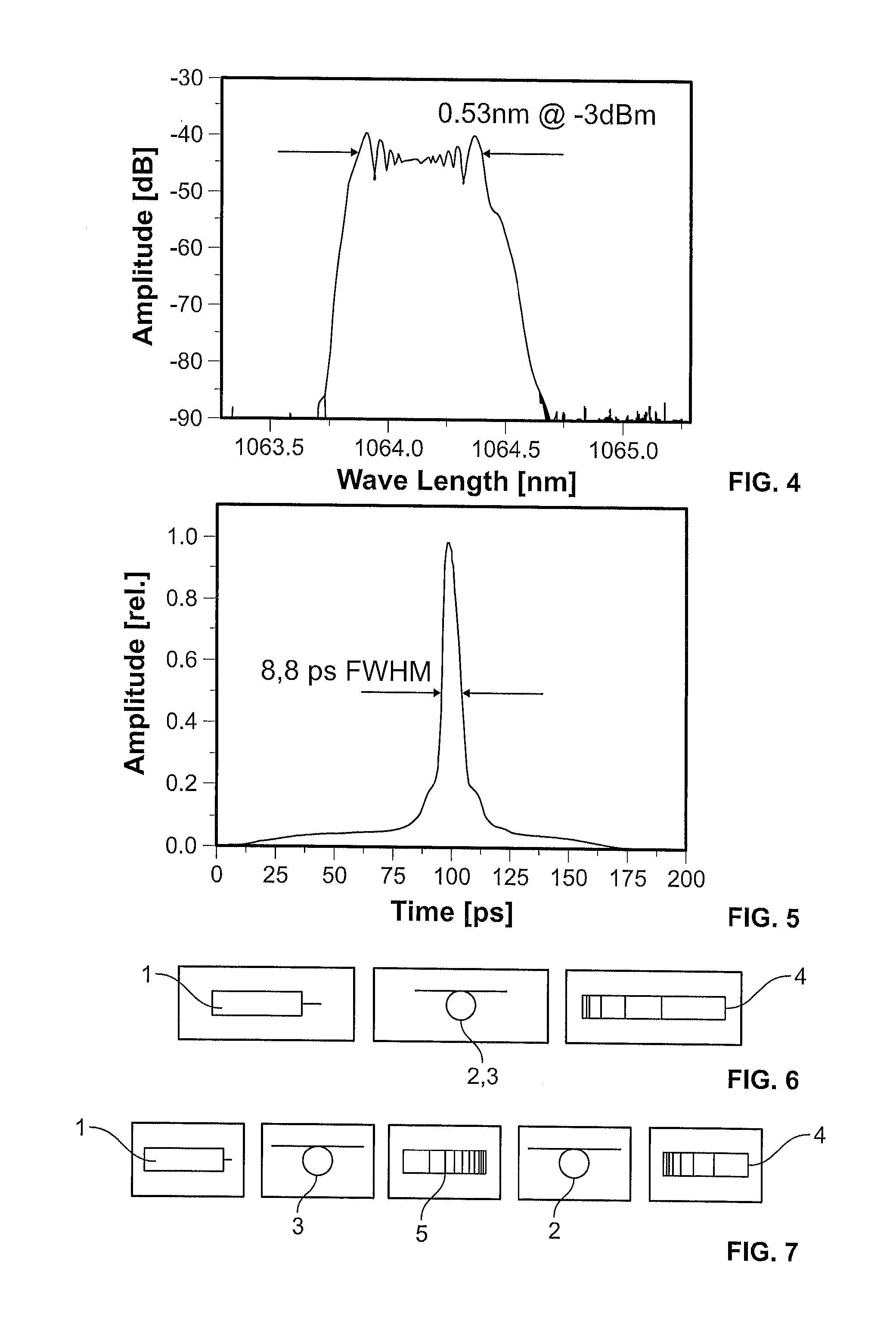
[0025]In FIG. 6, the laser system is comprised of a laser 1, an amplifier 2 which at the same time is the spectrally widening element 3, and a compression element 4. Here, the spectrally widening amplifier 2, 3 may be an optical fiber which amplifies the laser pulse of laser 1 and which at the same time broadens it spectrally by self-phase modulation. The compression element 4 is a volume Bragg grating (VBG), a grating pair or a prism arrangement.

[0026]FIG. 7 shows a set-up comprised of a laser 1, a spectrally widening element 3 in form of a waveguide or an optical fiber, a temporal pulse extender 5—which may also be a VBG or a grating pair—, an amplifier 2 (e.g. a fiber with or without self-phase modulation), and a compression element 4.

[0027]The invention according to FIG. 1 in details works in a way that the passively Q-switched microchip laser 1 serves as signal source for the connecting fiber amplifier 2. The microchip laser 1 emits a mean output of 50 mW with a pulse duration ...


PUM


Abstract

The invention relates to a laser system with a passively Q-switched laser 1, a spectrally widening element 3, and a compression element 4. Laser systems of this kind are utilized for generating ultra-short laser pulses. Systems, mode-coupled solid-state lasers known from prior art allow for generating laser pulses in the sub-10 ps range only with complicated and alignment-sensitive free-beam arrangements. Therefore, it is the object of the present invention to create a laser system that generates pulse durations of less than 10 ps and which is simple and compact to produce at the same time. In order to achieve this object, the present invention proposes that the passively Q-switched laser 1 is provided with a longitudinally monomode output radiation which is spectrally widened by means of the spectrally widening element 3 by self-phase modulation and is temporally compressed by the compression element 4.

Description

CROSS REFERENCE TO RELATED APPLICATIONS[0001]This application is the National Stage of PCT / EP2011 / 001859 filed on Apr. 13, 2011 which claims priority under 35 U.S.C. §119 of German Application Nos. 10 2010 014 998.5 filed on Apr. 14, 2010, and 10 2010 021 262.8 filed on May 21, 2010, the disclosures of which are incorporated by reference. The international application under PCT article 21(2) was not published in English.BACKGROUND OF THE INVENTION[0002]1. Field of the Invention[0003]The invention relates to a laser system with a passively Q-switched laser, a spectrally widening element, and a compression element.[0004]2. Description of the Related Art[0005]Laser systems of this kind are intended to be utilized for generating ultra-short laser pulses. In prior art, only complicated mode-coupled laser systems are hitherto known which may achieve a pulse duration of under 10 ps. Hence a simple and compact solution to generate laser pulses in the sub-10 ps range offers a substantial mar...

Claims


Application Information

Patent Timeline
IPC IPC(8): H01S3/11G02F1/35H01S3/00H01S3/067H01S3/113H01S3/16
CPCH01S3/11H01S3/0057G02F1/353H01S3/0092H01S3/06754H01S3/113H01S3/1618
Inventor NODOP, DIRKSTEINMETZ, ALEXANDERLIMPERT, JENSTUENNERMANN, ANDREAS
Owner FRAUNHOFER GESELLSCHAFT ZUR FOERDERUNG DER ANGEWANDTEN FORSCHUNG EV
Why Eureka
Try Eureka