
Respiratory assistance apparatus

a technology of respiratory assistance and apparatus, which is applied in the direction of respirators, light and heating apparatus, drying machines, etc., can solve the problems of not being able to easily clean, components cannot be easily removed from the apparatus for cleaning, and the removal of components introduces a risk of damage to the components or the apparatus

Active Publication Date: 2015-12-17
FISHER & PAYKEL HEALTHCARE LTD
View PDF3 Cites 19 Cited by
  • Summary
  • Abstract
  • Description
  • Claims
  • Application Information

AI Technical Summary

Benefits of technology

The patent describes an apparatus that detects the presence of a chamber and prevents vapor from entering the housing. It also controls the compressor to slowly release any remaining vapor and provide a higher flow rate for accelerated drying and cooling. The technical effect is the improvement in efficiency and safety during the disinfection process.

Problems solved by technology

It is a problem in any such environment to keep a respiratory assistance apparatus clean and free from potentially harmful bacteria.
However, it is often necessary to clean the components in the subsequent gases flow path that are subjected to moisture, because moisture is susceptible to carrying bacteria which can cause the establishment and growth of biofilms that can be transmitted to the patient.
Whilst some components are accessible and therefore can be relatively easily cleaned (e.g., some patient interfaces may be placed in a dishwasher), other components are contained within the housing, or may have internal features that are difficult to access, and thus are not easily cleaned.
In some cases, components cannot easily be removed from the apparatus for cleaning, or at least not without specialist or relatively skilled personnel.
Removal of components also introduces a risk of damage to the components or the apparatus, or of incorrect refitting of the components after cleaning.

Method used


Image

  • Respiratory assistance apparatus
  • Respiratory assistance apparatus
  • Respiratory assistance apparatus

Examples


Embodiment Construction

[0100]Throughout the description like reference numerals will be used to refer to like features in different embodiments.

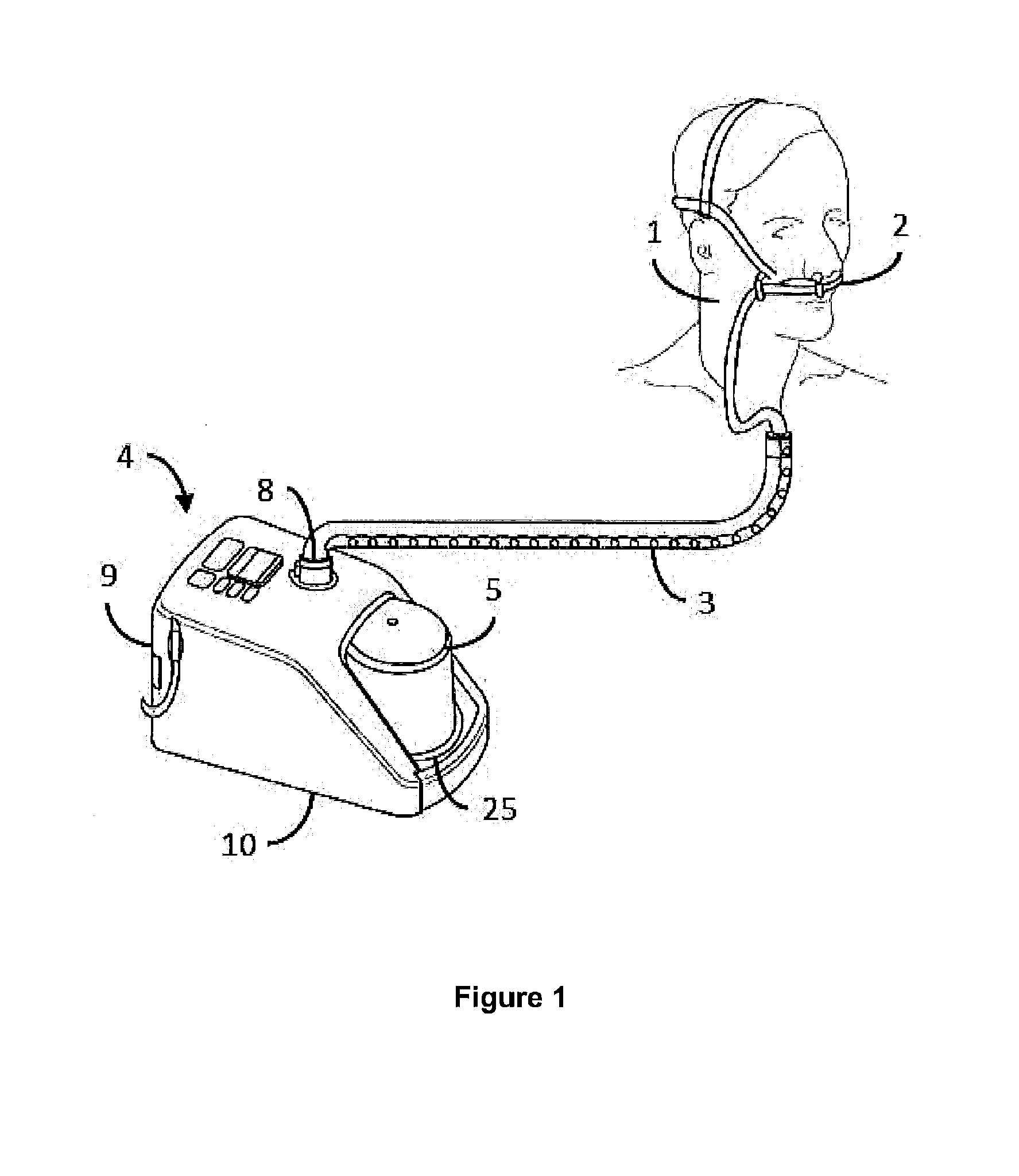
[0101]The present invention provides a respiratory assistance apparatus that provides a convenient, effective and reliable method of disinfecting at least a portion of the apparatus with moist heat during a disinfection mode, which portion may define, at least in part, a transport path for a humidified gases flow generated by the apparatus. According to some embodiments, the at least a portion of the apparatus comprises an internal passageway provided at least partially inside the apparatus. The present invention also provides a method of disinfecting a respiratory assistance apparatus and attachments for use with such method of disinfecting the respiratory assistance apparatus.

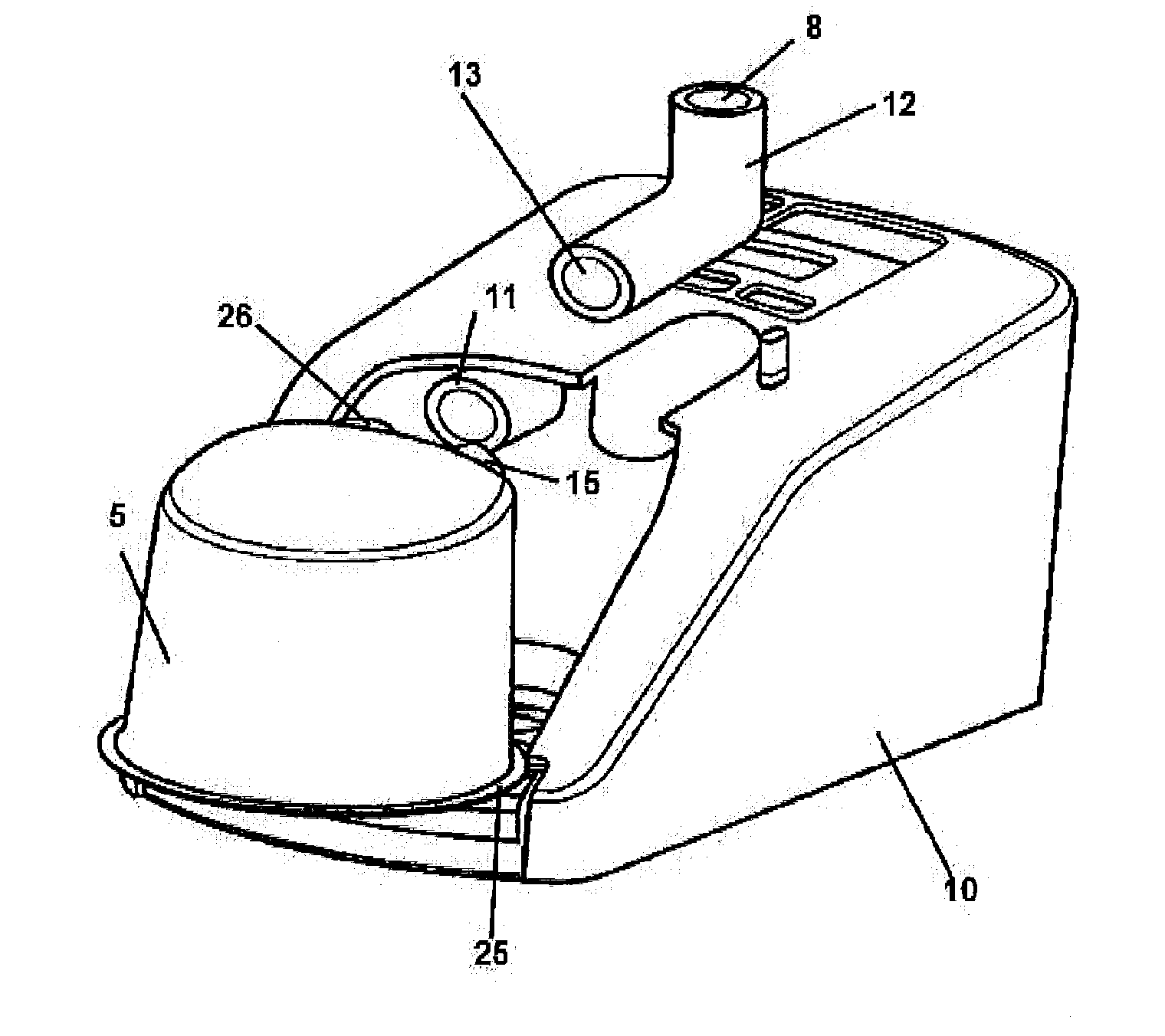
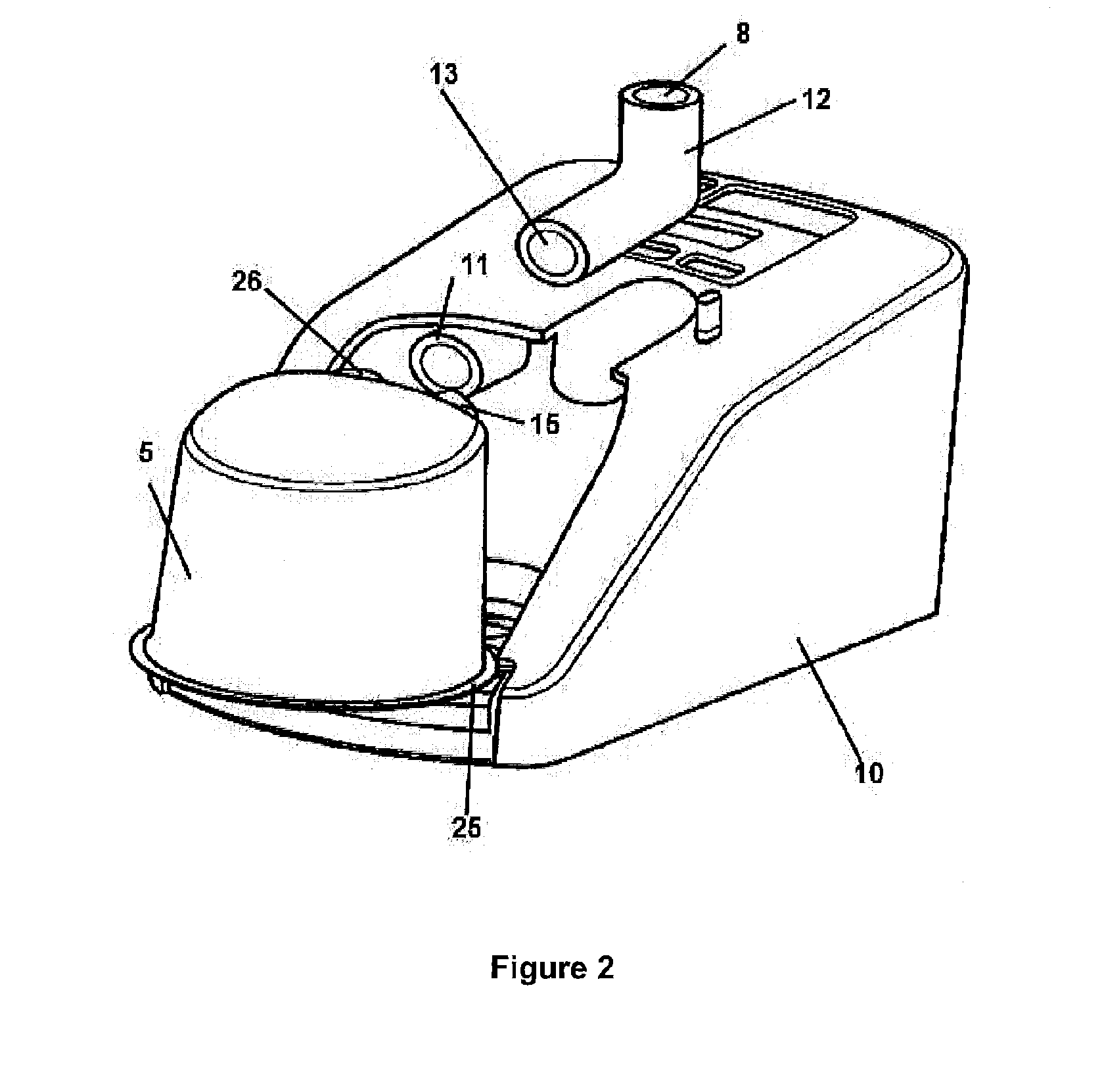
[0102]A chamber is provided on or at the apparatus in which liquid can be heated to produce vapour or steam, the vapour being delivered to the at least a portion of the apparatus (such as t...


PUM


Abstract

A respiratory assistance apparatus (4) is provided, adapted to deliver gases to a user or patient (1). The apparatus (4) comprises a housing (10) provided with a chamber (5) and a heater (25), the chamber (5) comprising at least one gas port (15) connected to, or arranged to be connected to, at least one intermediate passageway (12). The apparatus (4) is operative according to a disinfection mode of predetermined profile in which the heater (25) heats liquid in the chamber (5) to produce vapour at or above a target dewpoint temperature and / or humidity level. The apparatus (4) is arranged such that the vapour is delivered to the intermediate passageway (12) to disinfect the intermediate passageway (12) with moist heat throughout a predetermined duration of the disinfection mode. Associated attachments and methods are also provided.

Description

CROSS-REFERENCE TO RELATED APPLICATIONS[0001]This application claims priority from U.S. Provisional Application No. 61 / 758,663, filed on 30 Jan. 2013, the contents of which are incorporated herein by reference.BACKGROUND OF THE INVENTION[0002]1. Field of the Invention[0003]This invention relates to a respiratory assistance apparatus adapted to deliver respiratory gases to a user or patient. More particularly, the invention relates to a respiratory assistance apparatus provided with a disinfection mode and a method of disinfecting a respiratory assistance apparatus using a disinfection mode.[0004]2. Description of the Related Art[0005]A respiratory assistance apparatus typically comprises a humidifier, a gases inlet to supply a gases flow from a gases source to the humidifier, and a patient outlet to deliver a gases flow from the humidifier to the user or patient. The gases source can be a blower, fan, pressurised tank, compressor, or the like. An inspiratory tube can be connected be...

Claims


Application Information

Patent Timeline
IPC IPC(8): A61M16/10A61M16/00A61L2/24A61M39/20A61L2/07A61L2/20A61M16/16A61M16/08
CPCA61M16/1075A61M2205/3379A61M16/0003A61M16/0875A61M16/1055A61M16/0063A61M16/0808A61M16/0051A61M39/20A61L2/07A61L2/20A61L2/24A61M2205/36A61M2205/3334A61M2205/3368A61M2205/60A61M16/161A61M16/16A61M2016/0039A61M16/0069A61M16/109A61M16/1095A61M16/107A61M16/024A61M2209/10F26B21/001
Inventor BARKER, DEAN ANTONYBURGESS, RUSSEL WILLIAMHAWKINS, PETER GEOFFREY
Owner FISHER & PAYKEL HEALTHCARE LTD
Learn More