High performance autonomous hardware engine for inline cryptographic processing

a hardware engine and cryptographic processing technology, applied in the direction of instruments, unauthorized memory use protection, error detection/correction, etc., can solve the problems of processors not flexible, the application of high-grade tamper resistance can be quite expensive, and the processors are not flexibl

a hardware engine and cryptographic processing technology, applied in the direction of instruments, unauthorized memory use protection, error detection/correction, etc., can solve the problems of processors not flexible, the application of high-grade tamper resistance can be quite expensive, and the processors are not flexibl

US20150363333A1Inactive Publication Date: 2015-12-17TEXAS INSTR INC

Image

  • High performance autonomous hardware engine for inline cryptographic processing
  • High performance autonomous hardware engine for inline cryptographic processing
  • High performance autonomous hardware engine for inline cryptographic processing

Examples


Embodiment Construction

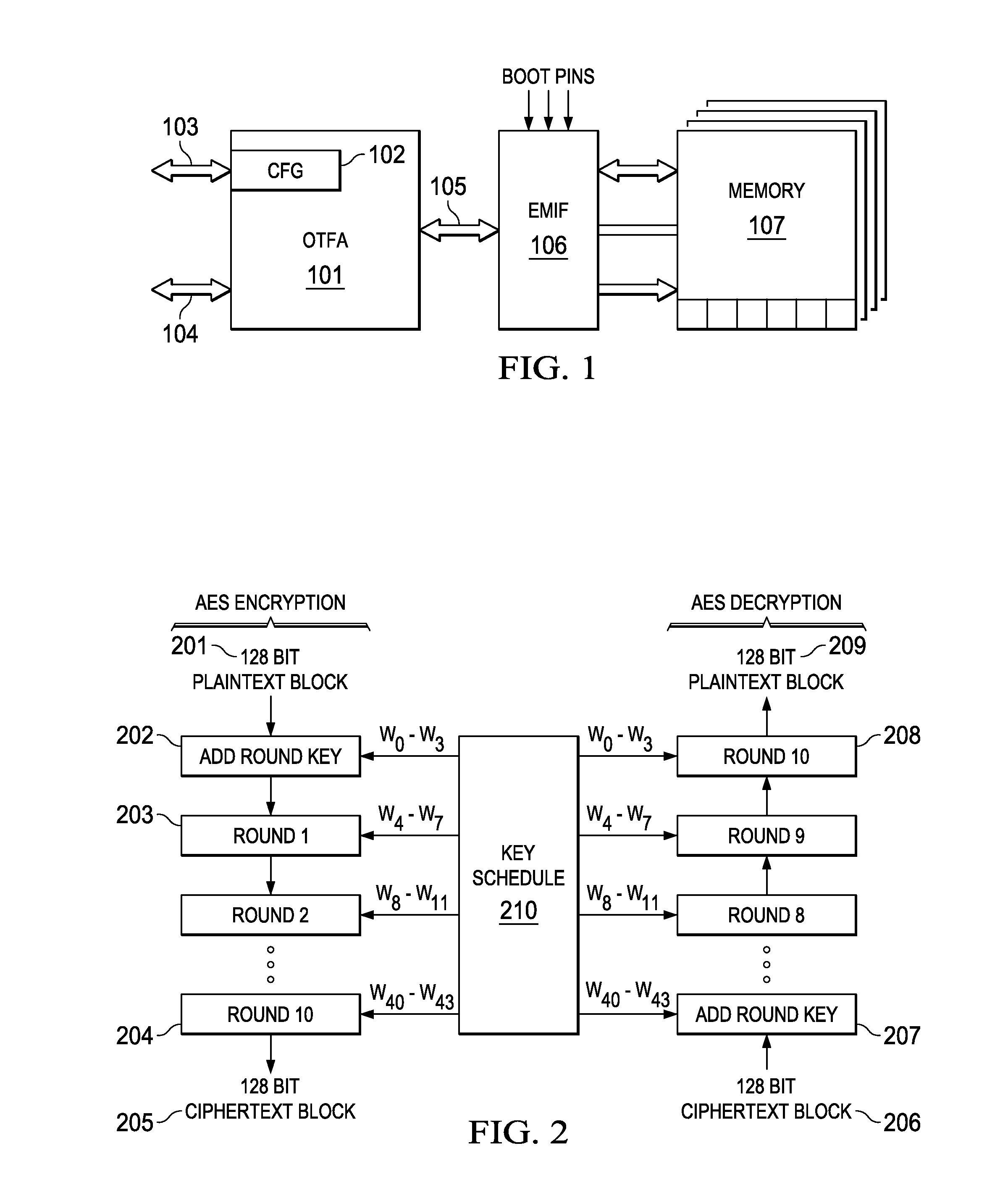
[0017]FIG. 1 shows the high level architecture of this invention. Block 101 is the on the fly encryption engine positioned between processor busses 103 and 14, and is connected to external memory interface 106 via bus 105. configuration data is loaded into configuration register 102 via bus 103, and unencrypted data is written / read to 101 via bus 104. Encrypted data is communicated to / from the External Memory Interface 106 via bus 105. External memory 107 is connected to and is controlled by 106. External memory 107 may be comprised of multiple memory segments. These segments may be unencrypted or encrypted, and the segments may be encrypted with distinct and different encryption keys.

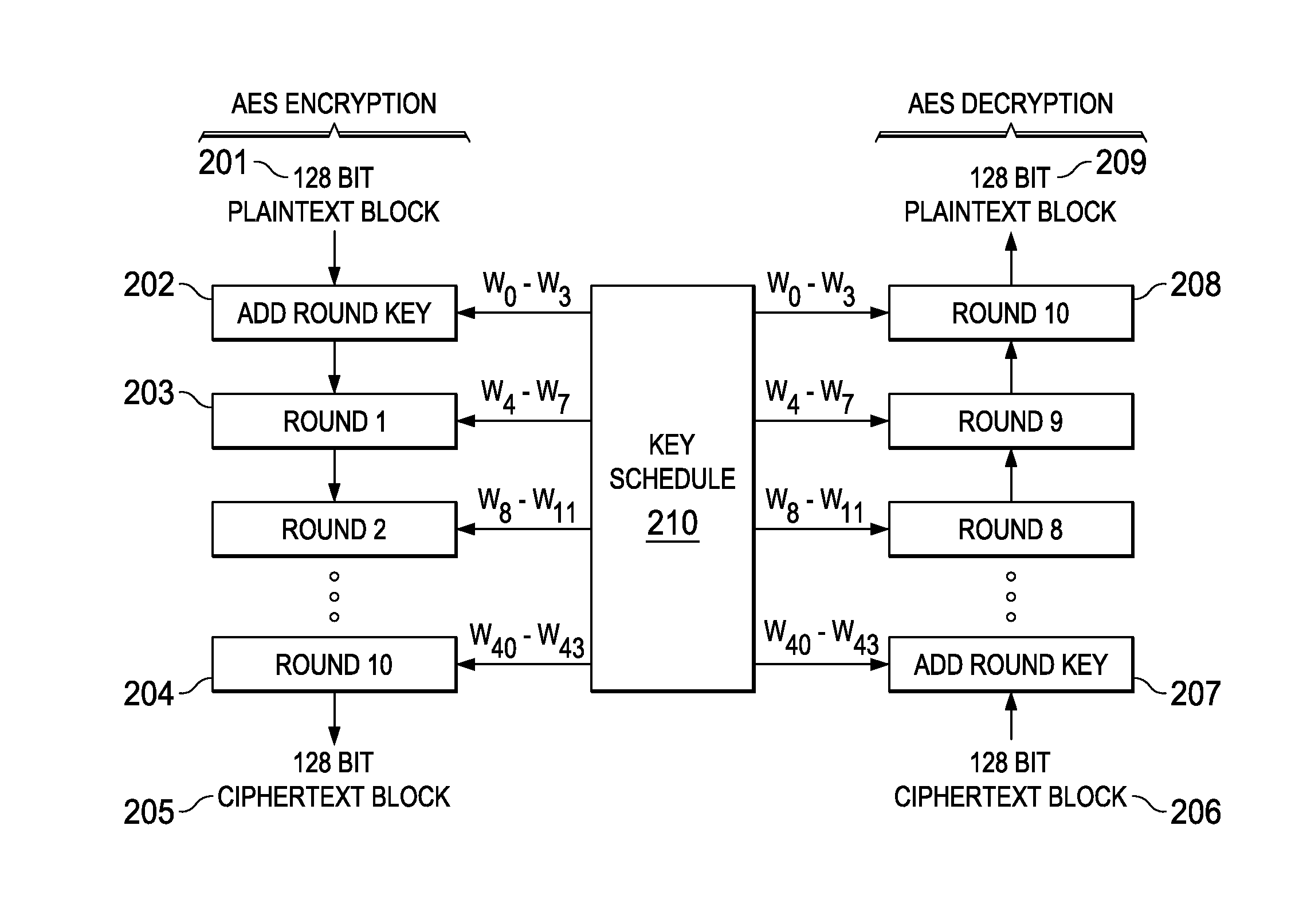
[0018]While there is no restriction on the method of encryption employed, the implementation described here is based on the Advanced Encryption Standard (AES).

[0019]AES is a block cipher with a block length of 128 bits. Three different key lengths are allowed by the standard: 128, 192 or 256 bits. Encr...


PUM


Abstract

A real time, on-the-fly data encryption system is shown operable to encrypt and decrypt the data flow between a secure processor and an unsecure external memory system. Multiple memory segments are supported, each with its own separate encryption capability, or no encryption at all. A Message Authentication Code is also employed to detect any memory corruption or unauthorized memory modification.

Description

BACKGROUND OF THE INVENTION[0001]Many emerging applications require physical security as well as conventional security against software attacks. For example, in Digital Rights Management (DRM), the owner of a computer system is motivated to break the system security to make illegal copies of protected digital content.[0002]Similarly, mobile agent applications require that sensitive electronic transactions be performed on untrusted hosts. The hosts may be under the control of an adversary who is financially motivated to break the system and alter the behavior of a mobile agent. Therefore, physical security is essential for enabling many applications in the Internet era.[0003]Conventional approaches to build physically secure systems are based on building processing systems containing processor and memory elements in a private and tamper-proof environment that is typically implemented using active intrusion detectors. Providing high-grade tamper resistance can be quite expensive. More...

Claims


Application Information

Patent Timeline
17 Dec 2015
Publication
US20150363333A1
IPC
G06F12/14; G06F13/28
CPC
G06F12/1408; G06F2212/1052; G06F13/28; G06F21/602; G06F2221/2107; G06F21/64; G06F21/85
Inventors
WALLACE, WILLIAM C.; MUNDRA, AMRITPAL S.