
Gas shower device, chemical vapor deposition device and method

Active Publication Date: 2015-12-24
ADVANCED MICRO FAB EQUIP INC CHINA
View PDF3 Cites 6 Cited by
  • Summary
  • Abstract
  • Description
  • Claims
  • Application Information

AI Technical Summary

Benefits of technology

The present invention is about a gas shower device that improves the quality of films formed using chemical vapor deposition. This device is simple and easy to use, and can help to make chemical vapor deposition more effective and efficient.

Problems solved by technology

However, the quality of the thin film formed by current metal organic chemical vapor deposition device is poor.

Method used


Image

  • Gas shower device, chemical vapor deposition device and method
  • Gas shower device, chemical vapor deposition device and method
  • Gas shower device, chemical vapor deposition device and method

Examples


Embodiment Construction

[0064]As mentioned in the background technology, the quality of the thin film formed by current metal organic chemical vapor deposition device is poor.

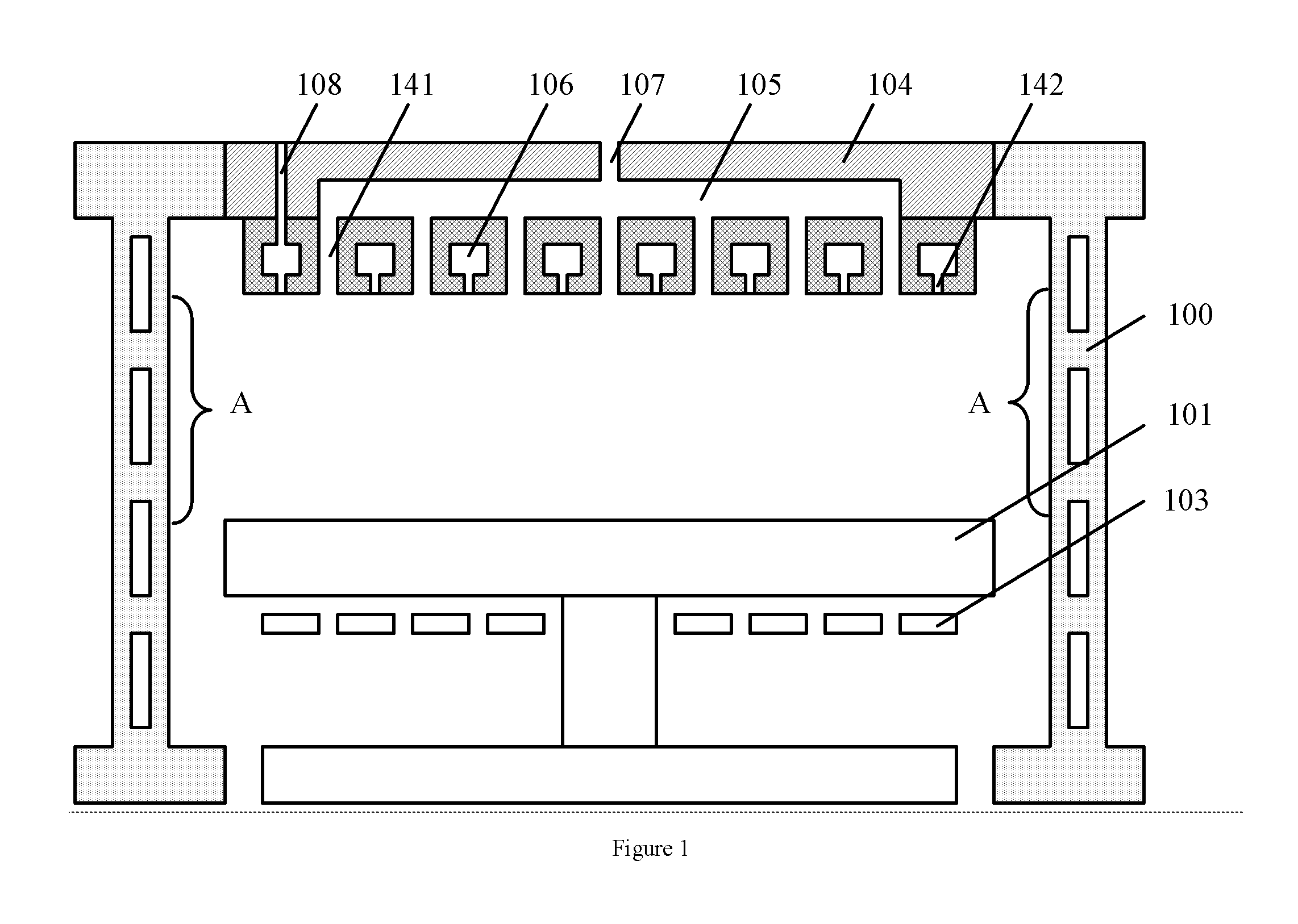
[0065]According to the research findings, refer to FIG. 1, FIG. 1 is the cross-sectional structure view of a metal organic chemical vapor deposition device of the embodiments of the present invention, including:

[0066]Reaction chamber 100;

[0067]The carrier 101 located in the reaction chamber 100, wherein, the carrier 101 could rotate along the axis, the carrier 101 surface is used to place the wafer to be processed; the carrier 101 bottom has heating device 103 which is used to heat the wafer placed on the carrier 101;

[0068]The shower module 104 is located on top of the reaction chamber 100, and the shower module 104 is set oppositely to the carrier 101; the first gas chamber 105 and the second gas chamber 106 are mutually isolated in the shower module 104; the shower module 104 surface facing towards the carrier 101 has the first gas-...


PUM

PropertyMeasurementUnit
Fractionaaaaaaaaaa
Flow rateaaaaaaaaaa
Diameteraaaaaaaaaa

Abstract

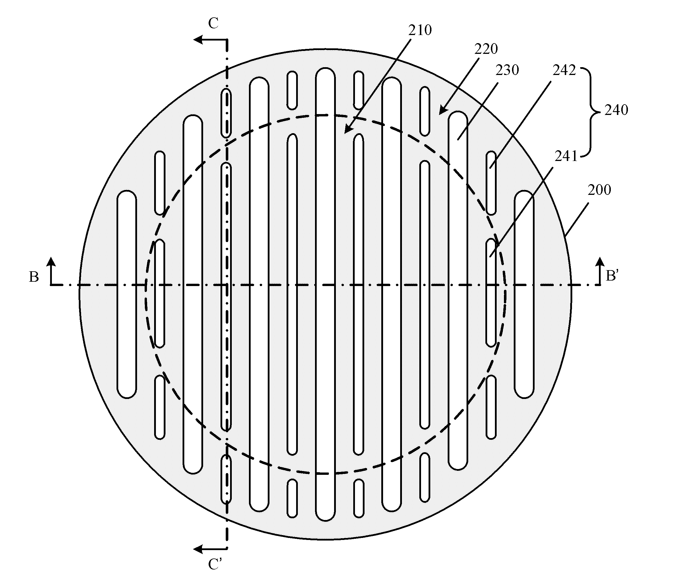
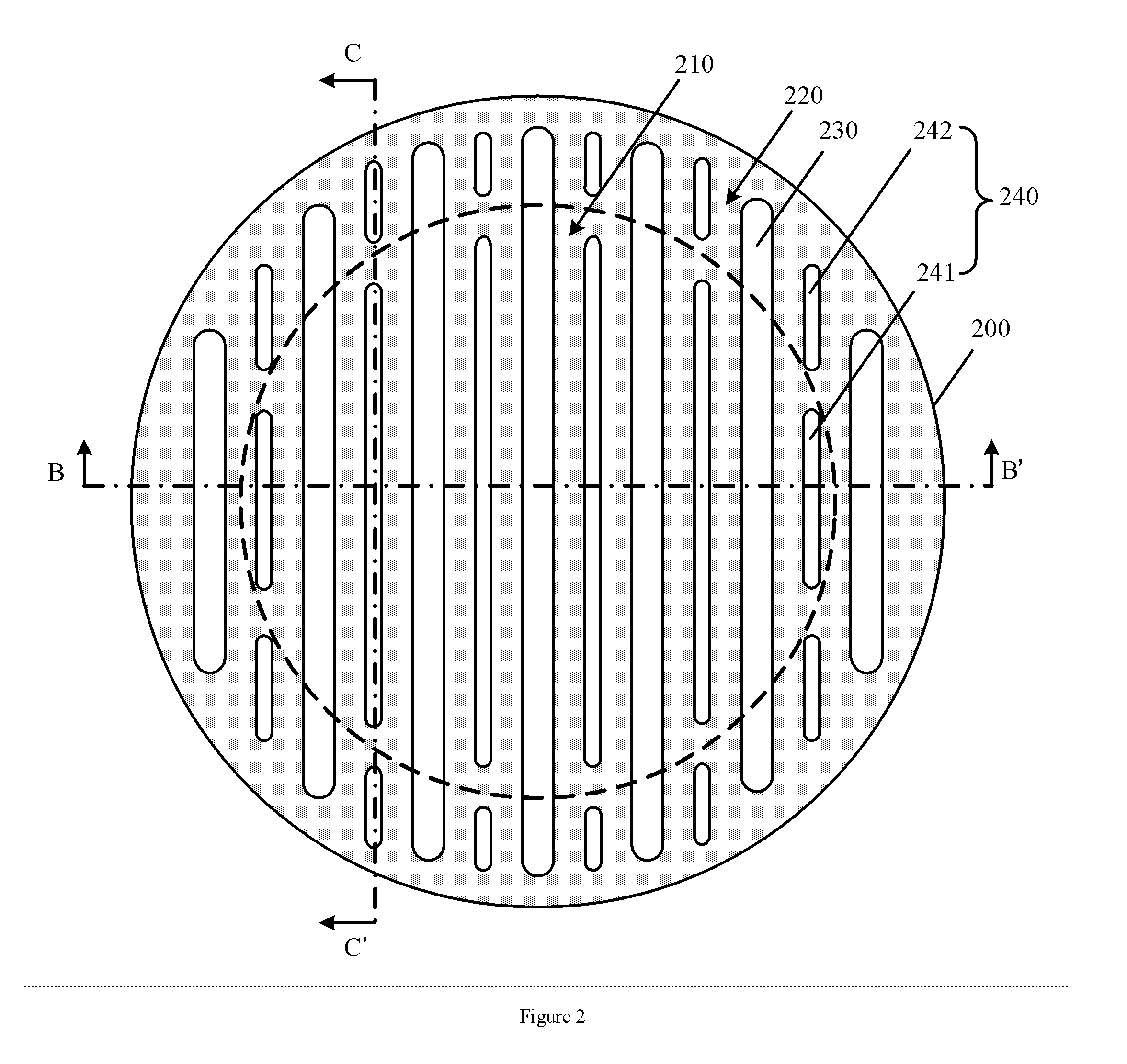
A gas shower device, a device and a method for chemical vapor deposition. A gas shower device has a showerhead. The showerhead includes a center region and a periphery region surrounding the center region; the center region and periphery region of the showerhead have a plurality of second gas-outlets which are arranged in parallel; the second gas-outlets are used to output the second gas; a first gas-outlet arranged between two adjacent second gas-outlets, includes the first sub-gas-outlet located in the center region and the second sub-gas-outlet located in the periphery region; the first sub-gas-outlet and the second sub-gas-outlet are mutually isolated, the first sub-gas-outlet is used to output the first gas and the second sub-gas-outlet is used to output the second gas; a first gas channel is connected to the first sub-gas-outlet; a second gas channel is connected to the second gas-outlet and the second sub-gas-outlet. The film formation quality is improved by using the chemical vapor deposition device with the gas shower device.

Description

CROSS-REFERENCE TO RELATED APPLICATIONS[0001]The present application claims benefit of Chinese Application No. 201410273262.5, filed Jun. 18, 2014, the contents of which are incorporated herein by reference.TECHNICAL FIELD[0002]The present invention relates to semiconductor manufacturing technical field, especially to a gas shower device, a device and a method for chemical vapor deposition.BACKGROUND TECHNOLOGY[0003]Chemical vapor deposition (referred to as CVD) is the process technology that the reaction substances react under the gaseous condition to generate solid substance deposited on the surface of the heated solid substrate, thereby to obtain solid material, which is achieved by using chemical vapor deposition device. In particular, CVD device introduces the reaction gases into the reaction chamber by using the inlet device, controls the pressure, temperature and other reaction conditions in the reaction chamber so that the reaction gases will react, to complete the depositio...

Claims


Application Information

Patent Timeline
IPC IPC(8): C23C16/455C23C16/22C23C16/44
CPCC23C16/45565C23C16/22C23C16/4412C23C16/45574
Inventor JIANG, YONGDU, ZHIYOU
Owner ADVANCED MICRO FAB EQUIP INC CHINA
Learn More