Structural/constructional element for floor systems

Active Publication Date: 2019-08-13
PAUL PETR +1
View PDF12 Cites 2 Cited by
  • Summary
  • Abstract
  • Description
  • Claims
  • Application Information

AI Technical Summary

Benefits of technology

[0043]Thanks to the new technical solution and construction system of the light panel according the invention—it is possible to build up arbitrary large lightning areas—e.g. extensive floorings (composed of unlimited quantity of light panels as constructional units), without disturbing the final surface with unsightly connecting particles like joints, junctions, construction-ledges or aluminum profiles—like in the case of present light-equipped floor systems, whose surface is always divided in squares (place for hiding of cable+accessories). Without the usage of this new light panel according to the invention, the optical and design properties of the floor surface are broken due to the squares which are formed from the AL-profiles as a base, bringing next typical negative feature—a very hard surface (glass as top-layer cover), because of any use/presence of dampening or impact absorbing elements, which would control the vibrations and absorb the shocks, caused by walking or dancing people (music clubs, dancing disco-halls). Hardness of such a floor has a very negative influence on the human body, especially women while wearing the high-heel shoes are often affected with health-problems in the form of lower back pain, lumbar or cervical spine and/or suffer with deformation of the foot arch! These negative effect doesn't occur in the case of installation of the new light panel according to the invention as flooring system, because t

Problems solved by technology

This classic method has a whole range of disadvantages, which are caused due to the choice of the underlying material—the wood.
These main disadvantages and weaknesses are: the whole flooring system based on the wooden grate has ordinarily an average height of 100 to 150 mm, whereby the majority of the space takes the wooden grate as itself.
This creates unwanted space pockets which must be afterwards filled and sealed by mineral wool or other form of heat or noise isolation.
Alternatively there is installed a ventilation system, placed under the floor in these pockets (needed an air circulation due to the wooden grate)=expensive installation and operation costs!
!), next big weakness of wood is all above its dimensional instability—swelling, expansion and changes in shape+volume related to variable humidity.
Biodegradable processes (rots, molds, micro-organisms)+highly sensitive material to humidity, which represents a big problem with transportation (water condensation, rain, evaporating .
. . etc.), wood worms, dry rots, pests—susceptibility especially during transport (psychopathological an

Method used


Image

  • Structural/constructional element for floor systems
  • Structural/constructional element for floor systems
  • Structural/constructional element for floor systems

Examples


Example

Example 1—Portable Variable Flooring for Sports Use

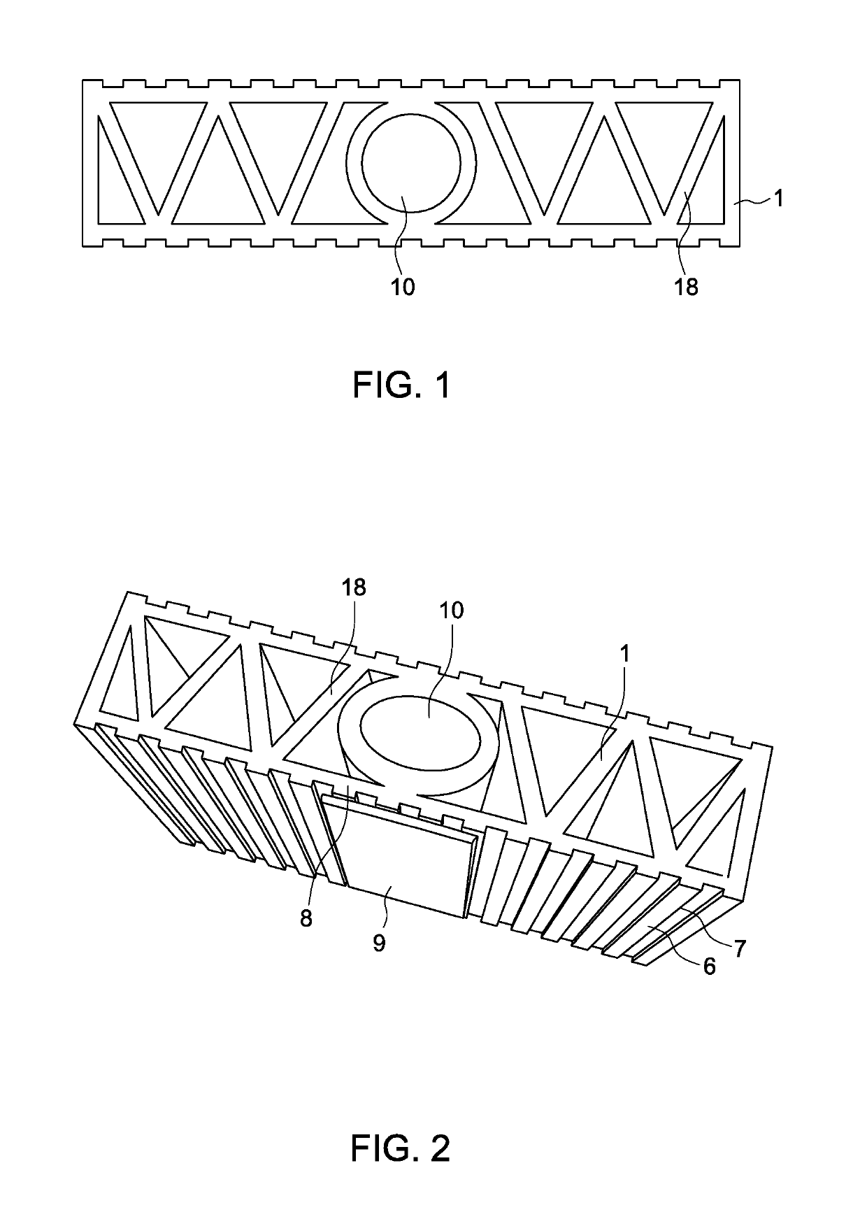
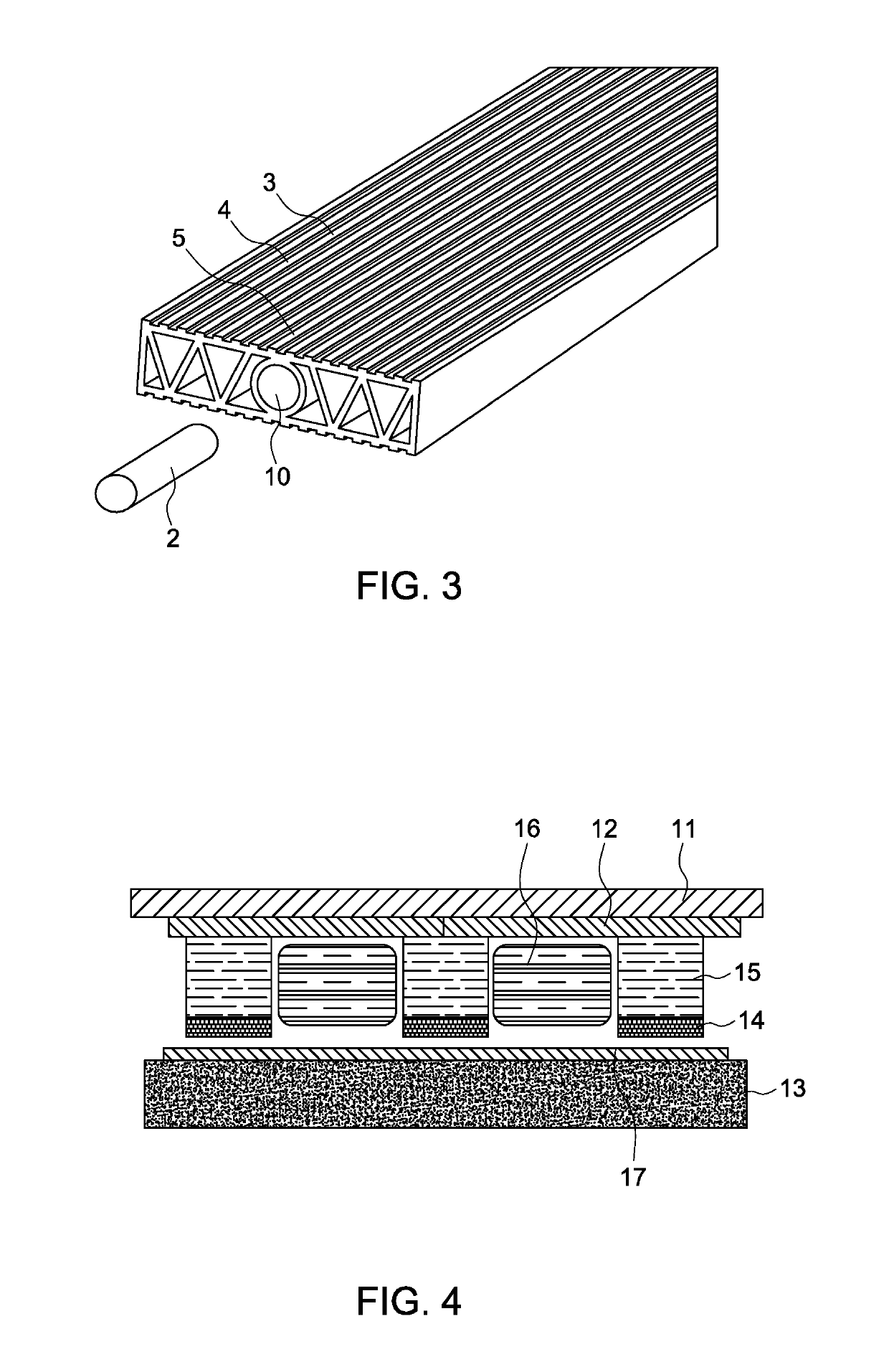
[0082]On a flat, stable surface in nature (garden, yard, playground . . . ) were laid strips of the structural / constructional element according to the invention the width of 80 mm and length of 1.25 m with a spacing of 0.24 m. Primary part 1 of this element was hallow and with inner reinforcement in the form of ribbing 18 in the shape WOW, which provides connectivity of the structural / constructional elements by inserting a central pin 2 so that the cross-section of the pin 2 corresponds to the hole 10 between the ribs 18. The structural / constructional elements were fitted on the upper surface 3 by the anti-slip longitudinal grooves 4 a depth of 2 mm and width of 5 mm and a white a central groove 5 on the upper surface 3 and lower surface 6 was also fitted with an anti-slip grooves 7 as the upper surface 3 the structural / constructional element according to the invention. The white color on a central groove 5 can be applied imprinted ...

Example

Example 2—Renovation of the Balcony Floor

[0085]For the renovation of the balcony floor were the structural / constructional element according to the invention and the example 1 laid freely on a flat, stable surface. The size of the balcony floor was 3.6 m×0.85 m.

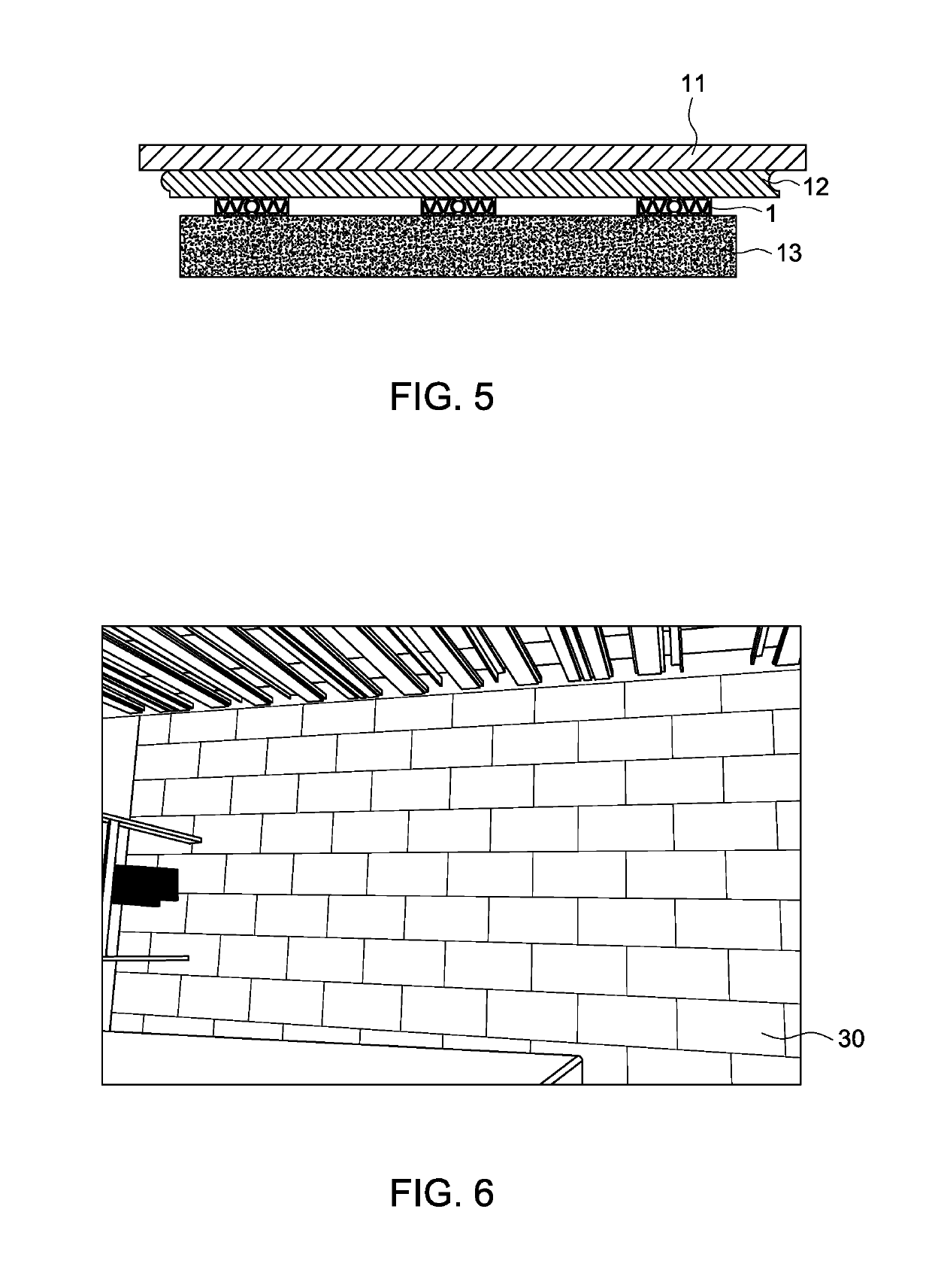
[0086]The structural / constructional element according to the invention was cut and laid on the floor 4× in whole the size of 850×80 mm, 3× in whole the size of 400 mm×80 mm, 1 piece of 200 mm×80 mm and 24 pieces of 80 mm×80 mm. On top of this were laid a layer of impregnated OSB panels 12 with a thickness of 15 mm and on them was fixed PVC covering 11 with double-sided adhesive tape as shown in FIG. 11.

Example

Example 3—Laying of the Terrace Floor

[0087]For laying of the unroofed terrace floor were the structural / constructional element according to the invention and the example 1 laid freely on a flat, stable surface. The size of the terrace was 2.2 m×0.96 m, as shown in FIG. 9 from the laying of 15.1.2016.

[0088]The structural / constructional element according to the invention was cut and laid on the floor 7× in whole the size of 300×80 mm, 12 pieces of 80 mm×80 mm and 1 piece of 20 mm×80 mm. On top of this were laid a layer of impregnated OSB panels 12 with a thickness of 15 mm and on them was fixed PVC covering 11 with double-sided adhesive tape.


PUM

PropertyMeasurementUnit
Lengthaaaaaaaaaa
Lengthaaaaaaaaaa
Fractionaaaaaaaaaa

Abstract

A structural element, including a base portion and a connecting central pin, has its base portion formed hallow, and having an internal reinforcement in the shape of WOW or MOM, to connect these elements with an insertable central pin so that the cross-section of the pin corresponds to the shape of the chamber between the reinforcements, when the upper surface of the structural element has longitudinal grooves, and is made from a modified polymer or elastomeric material comprising India rubber mixtures. The foundation is monomer ethylene propylene diene or natural rubber or styrene-butadiene rubber and/or combinations of the natural rubber/styrene-butadiene rubber, or thermoplastic elastomers, whose base is monomer ethylene-propylene-diene or polypropylene/monomer ethylene-propylene-diene or polyvinylchloride, or thermoplastic vulcanizates, whose base is monomer ethylene-propylene-diene and polyethylene or natural and/or synthetic rubber, modified by polyethylene or polypropylene.

Description

BACKGROUND OF THE INVENTION[0001]The present invention relates to a structural material or element and, more particularly, to a material / element with improved construction properties.[0002]Technical Section[0003]This invention relates to structural / constructional element, which is applicable especially as a constructional, underlying, dampening, shock-absorbing and insulating material for diverse floor systems—its use is universal and its application is intended for following flooring systems: parquet, wooden, laminate-floating, vinyl, linoleum, casting epoxy, PUR+ other multi-layer polymer combinations, PVC flooring, sports flooring and self-leveling, multifunctional, industrial floors.[0004]The solution relates also to the light panel according to CZ PV 2017-45, which shows a unique functional properties and is resistant to mechanical pressure or impact or shock.[0005]Note: Throughout the specification, reference is made to measurements in the metric system, using S.I. units of me...

Claims


Application Information

Patent Timeline
IPC IPC(8): F21S8/02F21V3/06E04F15/022H05B37/02H05B33/08F24D13/02F21V33/00E04F15/22E04F15/20E04F15/18E04F15/10E04F15/02B32B27/08A63C19/00G08B7/06A47C21/06H05B44/00
CPCE04F15/225B32B27/08E04F15/022E04F15/02183E04F15/105E04F15/185E04F15/20F21S8/022F21V3/062F24D13/024H05B33/0854H05B33/0872H05B37/0236H05B37/0272A63C19/00Y02B30/26A47C21/06B32B2307/402B32B2307/412B32B2307/414B32B2309/105E04F2015/0205E04F2201/0505E04F2203/04F21V33/006G08B7/066Y02B30/00H05B45/20H05B47/12
Inventor PAUL, PETRCHOVANEC, PAVEL
Owner PAUL PETR
Why Eureka
Try Eureka