Fuel injection system for internal combustion engine

a fuel injection system and internal combustion engine technology, applied in the direction of machines/engines, electrical control, mechanical equipment, etc., can solve the problems of small injection amount, irregular injection amount, short needle valve opening time, etc., and achieve the effect of reducing the number of maximum partial lift injections that can be executed in a single injection stroke and shortening the suitable fuel injection tim

Inactive Publication Date: 2015-12-24
TOYOTA JIDOSHA KK
View PDF13 Cites 5 Cited by
  • Summary
  • Abstract
  • Description
  • Claims
  • Application Information

AI Technical Summary

Benefits of technology

[0018]According to the configuration described above, the maximum partial lift injection can be executed to the maximum extent possible within a range in which the injection amount of the maximum partial lift injection does not exceed the target amount. Accordingly, the fuel injection control can be performed with the high-accuracy maximum partial lift injection utilized to the maximum extent possible even during the partial lift injection.
[0019]The electronic control unit may be configured to a) calculate a plurality of times that the maximum partial lift injection is executable in one fuel injection cycle based on an engine rotational speed, and b) set the number of times that the maximum partial lift injection is executed in one fuel injection cycle, to one of the calculated numbers of times.
[0020]The period suitable for the fuel injection is shortened as the engine rotation speed increases. Accordingly, the number of maximum partial lift injections that can be executed in a single injection stroke decreases. As a result, the set number of maximum partial lift injections may not be completely executed during the period suitable for the fuel injection when the engine rotation speed is high.
[0021]In contrast, according to the configuration described above, the number of executions of the maximum partial lift injection is set within a range of the number of the possible executions calculated based on the engine rotation speed. Accordingly, the incomplete execution of the set number of maximum partial lift injections during the period suitable for the fuel injection can be inhibited.
[0022]The electronic control unit may be configured to set the number of times that the maximum partial lift injection is executed in one fuel injection cycle, to the largest number of times from among the calculated numbers of times.
[0023]According to the configuration described above, the maximum partial lift injection can be executed to the maximum extent possible within a range of the number of the possible executions calculated based on the engine rotation speed with the injection amount of the maximum partial lift injection not exceeding the target amount. Accordingly, the fuel injection control can be performed with the high-accuracy maximum partial lift injection utilized to the maximum extent possible while the incomplete execution of the set number of maximum partial lift injections during the period suitable for the fuel injection can be inhibited.

Problems solved by technology

However, the period during which the needle valve is open is short and the injection amount is small in the case of the partial lift injection during which the energization is terminated before the needle valve reaches the fully-open state.
Accordingly, a deviation in the valve-open period and the valve-opening speed largely affect the injection amount and the injection amount is likely to become irregular.

Method used


Image

  • Fuel injection system for internal combustion engine
  • Fuel injection system for internal combustion engine
  • Fuel injection system for internal combustion engine

Examples


Embodiment Construction

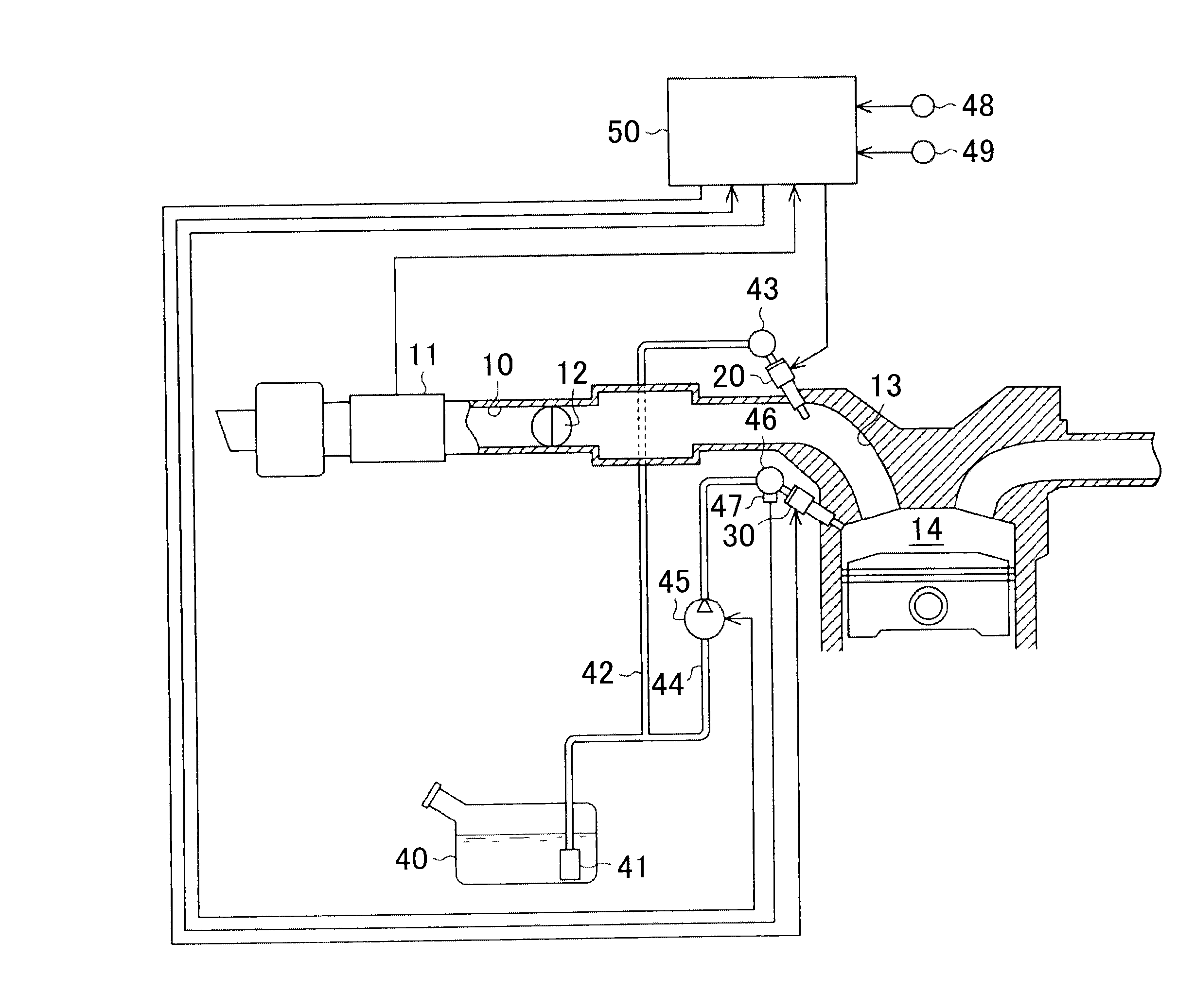
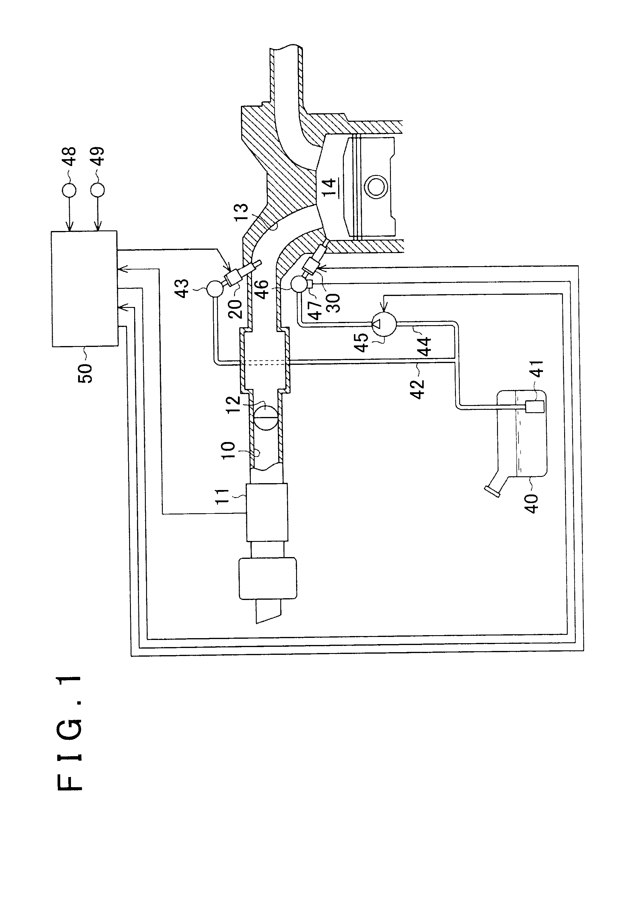
[0032]Hereinafter, an embodiment of a fuel injection system for an internal combustion engine will be described with reference to FIGS. 1 to 5. As illustrated in FIG. 1, an air flow meter 11 that detects an intake air amount and a throttle valve 12 that adjusts the intake air amount are arranged, in order from an upstream side, in an intake passage 10 of an internal combustion engine. The intake passage 10 branches on a further downstream side than the part where the throttle valve 12 is arranged and is connected to combustion chambers 14 for respective cylinders via intake ports 13.

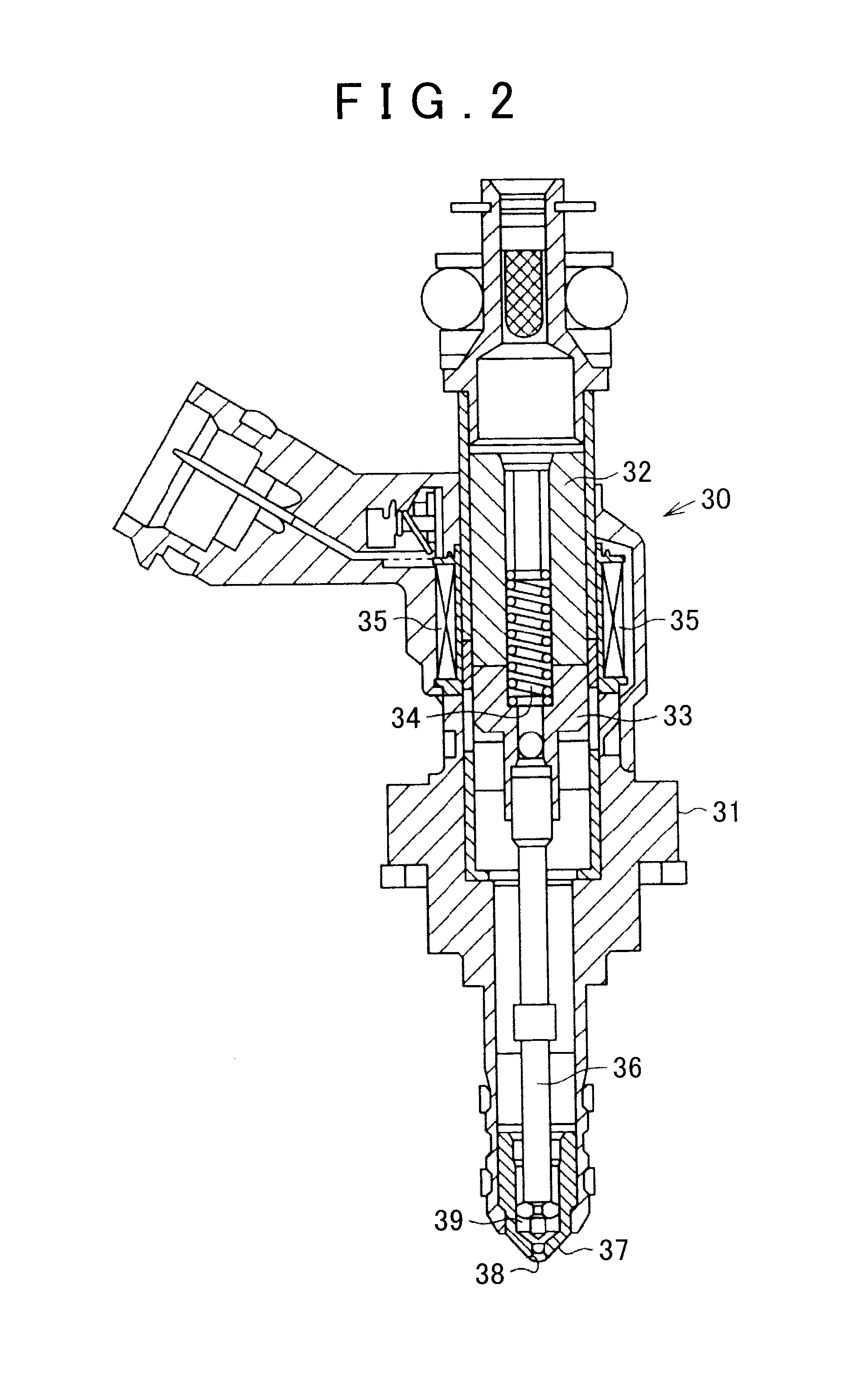
[0033]Port injectors 20 for fuel injection into the intake ports 13 are arranged in the respective intake ports 13 for the respective cylinders. In-cylinder injectors 30 for fuel injection into the cylinders are arranged in the respective cylinders.

[0034]A feed pump 41 that pumps a fuel is arranged in a fuel tank 40 of the fuel injection system. The feed pump 41 is connected to a low-pressure fuel pipe 4...


PUM


Abstract

This fuel injection system includes a port injector, an in-cylinder injector, and a control device. The control device sets the number of executions of maximum partial lift injection per injection stroke based on the pressure of a fuel supplied to the in-cylinder injector and within a range of the number of injections in which an injection amount of the maximum partial lift injection per injection stroke becomes equal to or less than a target amount. This control device allows the in-cylinder injector to execute the number of executions of the maximum partial lift injection and allows the port injector to inject the fuel by the amount equal to the shortfall compared to the total injection amount only in the maximum partial lift injection by the in-cylinder injector.

Description

INCORPORATION BY REFERENCE[0001]The disclosure of Japanese Patent Application No. 2014-129290 filed on Jun. 24, 2014 including the specification, drawings and abstract is incorporated herein by reference in its entirety.BACKGROUND OF THE INVENTION[0002]1. Field of the Invention[0003]The invention relates to a fuel injection system for an internal combustion engine.[0004]2. Description of Related Art[0005]In order to improve exhaust properties, it is desirable to allow micro injection by decreasing the minimum injection amount per injection and realize a precise fuel injection control. However, as described in Japanese Patent Application Publication No. 2013-245576, an injection amount irregularity that is attributable to a bounce operation which is caused when a needle valve of an injector is fully open is likely to arise when the energizing time for the injector is shortened so as to decrease the injection amount per injection.[0006]In contrast, the micro injection can be realized ...

Claims


Application Information

Patent Timeline
Patent Type & Authority Applications(United States)
IPC IPC(8): F02D41/30F02M61/14F02M61/10
CPCF02D41/3094F02M61/145F02M61/10F02D41/402F02D2041/389F02D2200/0602F02D2200/101Y02T10/40
Inventor NAKANO, TOMOHIROMURASE, EIJI
Owner TOYOTA JIDOSHA KK
Why Eureka
Try Eureka