Residential HVAC control system

a control system and hvac technology, applied in the field of control systems, can solve the problems of increasing the complexity of many routine tasks, presently impossible for users to monitor many aspects of home heating, and strained homeowners' resources

Inactive Publication Date: 2015-12-24
TURNER IRA M
View PDF6 Cites 13 Cited by
  • Summary
  • Abstract
  • Description
  • Claims
  • Application Information

AI Technical Summary

Problems solved by technology

The increasingly fast-paced world makes accomplishing many routine tasks more complicated.
Unfortunately, some aspects of energy systems remain in an antiquated form.
That is, it is presently impossible for users to monitor many aspects of home heating.
Further, with the ever increasing cost of energy, the resources of homeowners are often strained during peak demand.

Method used


Image

  • Residential HVAC control system
  • Residential HVAC control system
  • Residential HVAC control system

Examples


Embodiment Construction

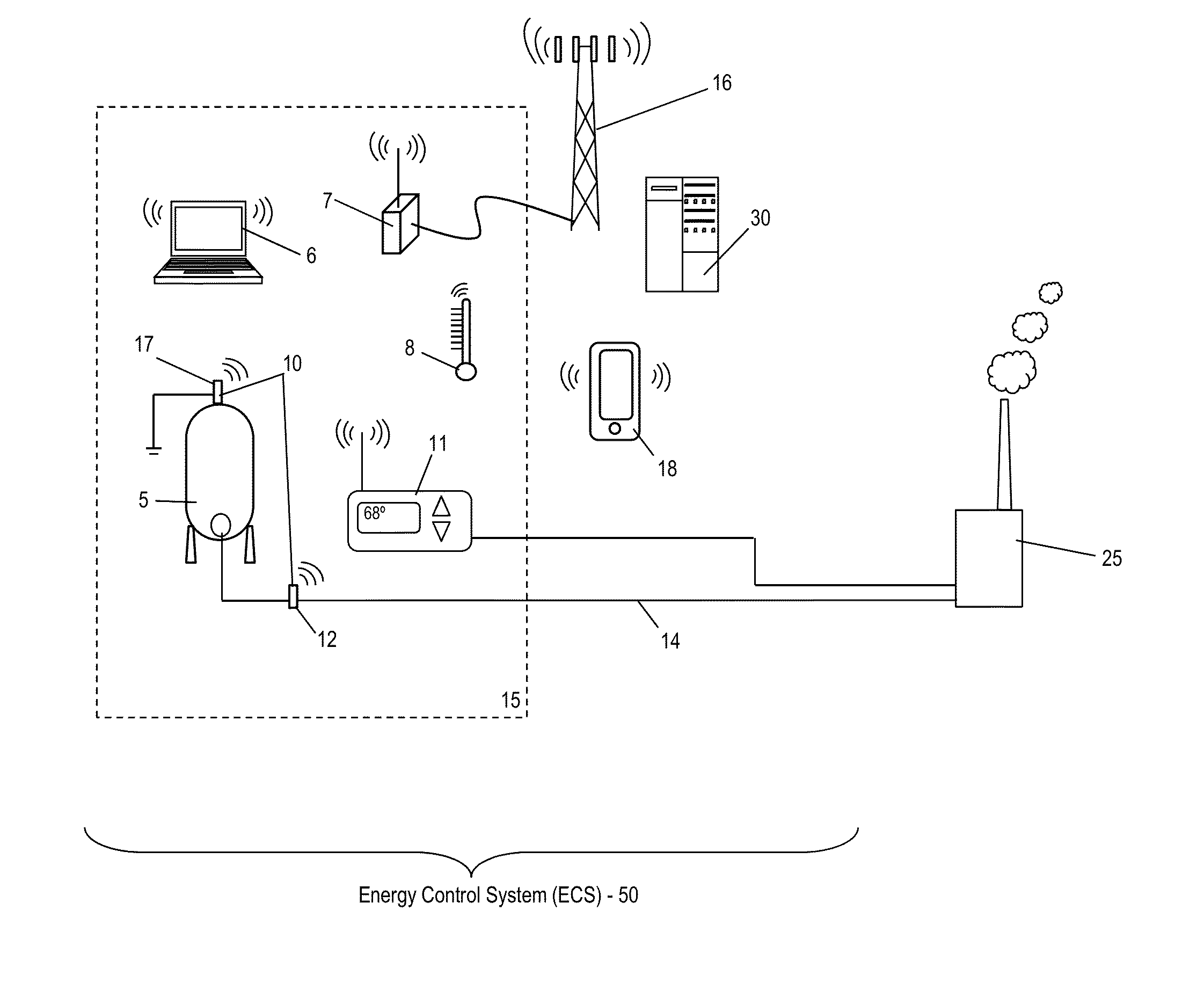
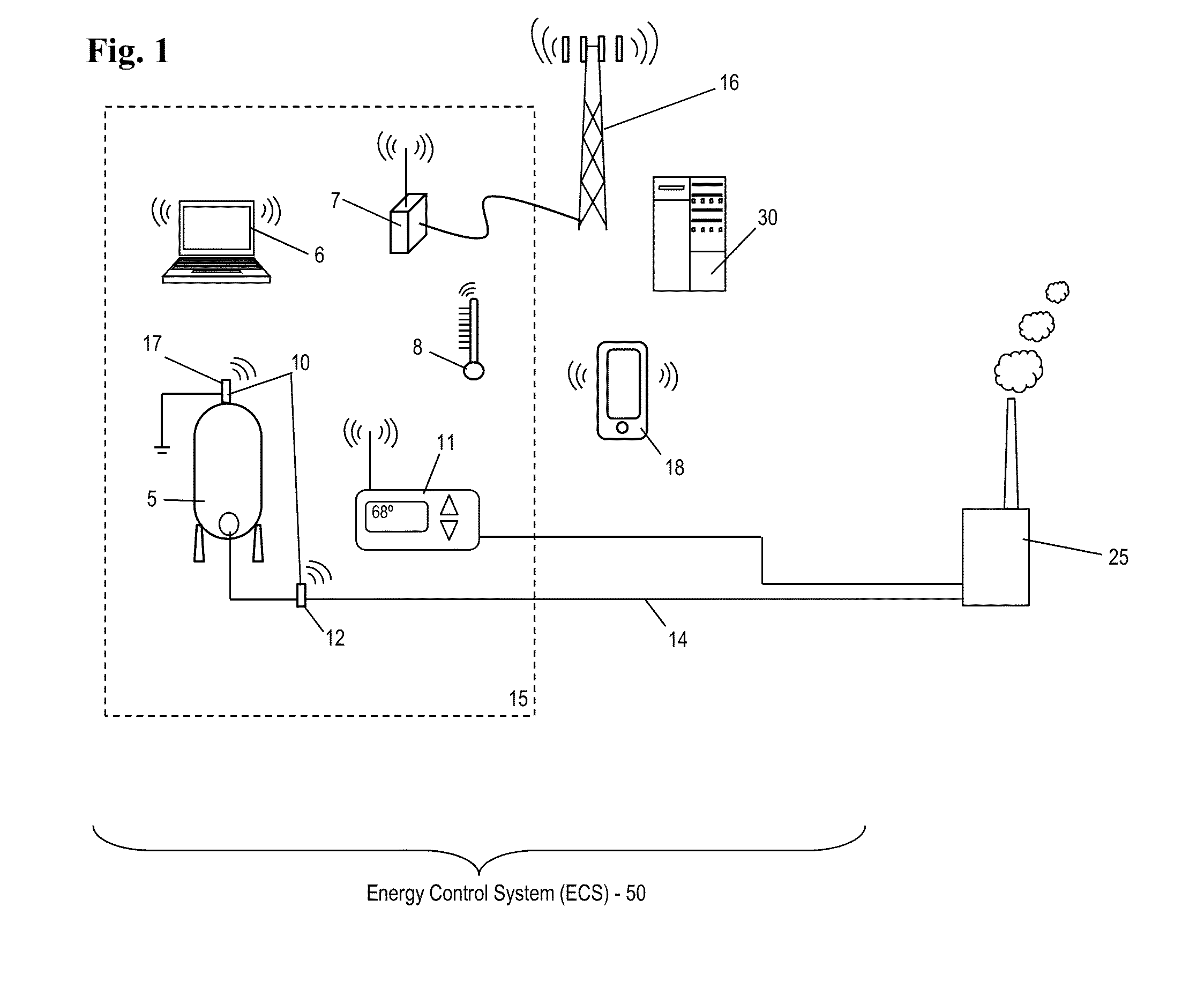
[0025]Disclosed herein are control systems for monitoring and controlling use of an energy supply according to a budget imposed by a user. The energy control systems disclosed provide for budgeting consumption of the energy supply in concert with a usage plan. Generally, a user will input settings to define the usage plan, and will also input control criteria for the system to budget use of the energy supply. Once an installation of the control system is operational, the usage plan will be modified as needed and on an ongoing basis to conform to the budget.

[0026]In an illustrative embodiment, the energy supply includes a tank full of home heating oil. The usage plan includes a heating schedule as may be input into a conventional programmable thermostat. The usage plan may include a series of days, times and corresponding temperature settings. The budget may include minimum refill date for the tank. More specifically, the budget may include the earliest date the user can afford to re...


PUM


Abstract

An energy control system is configured for regulating consumption of an energy supply by a residential heating, ventilation or air conditioning (HVAC) device. The energy control system includes a monitoring device configured for monitoring energy consumption by the residential HVAC device; a user interface for inputting a usage plan and inputting a budget for the energy supply; and a system controller for providing a revised usage plan by adjusting the usage plan to limit the energy consumption to conform with the budget.

Description

CROSS REFERENCE TO RELATED APPLICATIONS[0001]This application is filed under 35 U.S.C. §111(a) and 37 CFR 1.53(b), and claims under 35 U.S.C. §119(e) the benefit of prior-filed provisional applications No. 62 / 027202, filed Jul. 21, 2014, entitled “Feedstock Control System;” and, 62 / 014071, filed Jun. 18, 2014, entitled “Tank Monitoring System,” the disclosures of which are incorporated herein in their entireties.BACKGROUND OF THE INVENTION[0002]1. Field of the Invention[0003]The invention disclosed herein relates to control systems that monitor energy use and / or supply, process usage and other data to adjust energy consumption according to user defined criteria.[0004]2. Description of the Related Art[0005]The increasingly fast-paced world makes accomplishing many routine tasks more complicated. Consider that many people spend more and more time away from home. While this is often the case, the home is still a base of operations for everything else. Accordingly, many tools that provi...

Claims


Application Information

Patent Timeline
Patent Type & Authority Applications(United States)
IPC IPC(8): F24F11/00G05B15/02
CPCF24F11/006F24F11/0012F24F11/0086G05B15/02F24F2011/0094F24F2011/0047F24F2011/0057F24F2011/0064F24F2011/0068F24F2011/0013G05B2219/2614G05B2219/2639F24F11/30F24F11/56F24F2110/12F24F11/47F24F2120/20F24F2110/10F24F11/62F24F11/65F24F2140/60F24F11/52F24F11/58F24F11/46F24F11/63
Inventor TURNER, IRA M
Owner TURNER IRA M
Why Eureka
Try Eureka