Organic electroluminescence element, image-forming apparatus, display apparatus, and imaging apparatus

Active Publication Date: 2015-12-24
CANON KK
View PDF1 Cites 12 Cited by
  • Summary
  • Abstract
  • Description
  • Claims
  • Application Information

AI Technical Summary

Benefits of technology

The present invention aims to improve the emission efficiency of organic EL elements.

Problems solved by technology

However, no specific technology or approach for the optimization of the emission efficiency of the organic EL element through the utilization of the thickness and refractive index of the organic compound layer provided between the pair of electrodes has been established.

Method used


Image

  • Organic electroluminescence element, image-forming apparatus, display apparatus, and imaging apparatus
  • Organic electroluminescence element, image-forming apparatus, display apparatus, and imaging apparatus
  • Organic electroluminescence element, image-forming apparatus, display apparatus, and imaging apparatus

Examples


first embodiment

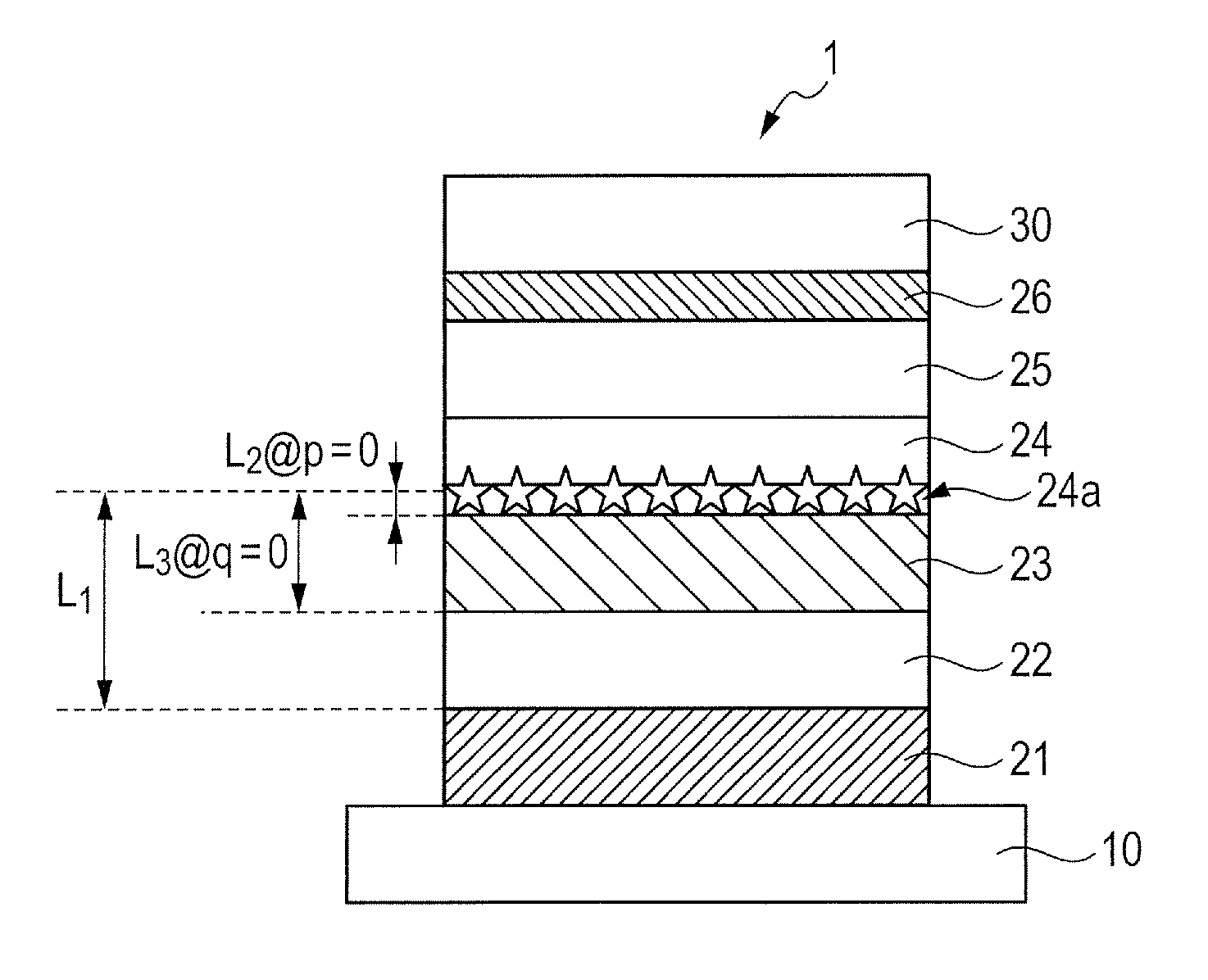
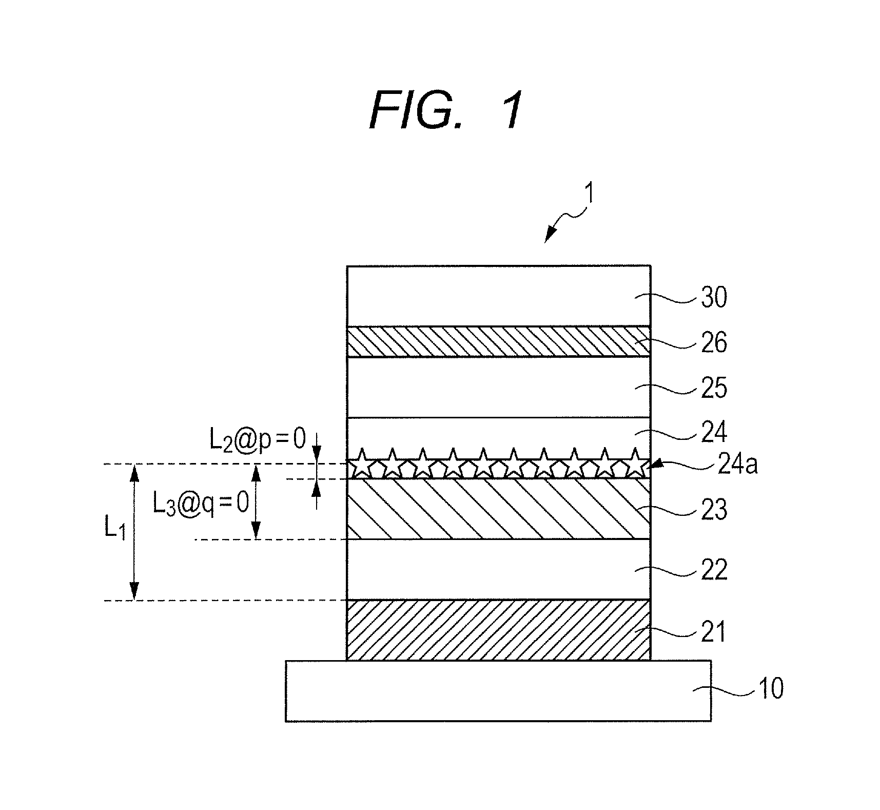
[0038]FIG. 1 is a schematic sectional view illustrating an organic EL element according to a first embodiment of the present invention. The organic EL element 1 of FIG. 1 is an electronic element obtained by laminating, on a substrate 10, a lower electrode 21, a first charge injection / transport layer 22, a second charge injection / transport layer 23, an emission layer 24, a third charge injection / transport layer 25, and an upper electrode 26 in the stated order. It is to be noted that in the organic EL element of the present invention, an optical adjustment layer 30 may be provided on the upper electrode 26 as illustrated in FIG. 1.

[0039]In the organic EL element 1 of FIG. 1, the lower electrode 21 functions as a reflective electrode. Accordingly, the organic EL element 1 of FIG. 1 is a top emission-type organic EL element in which light is extracted from a side opposite to the substrate 10. It should be appreciated that the present invention is not limited to the aspect, and a botto...

second embodiment

[0107]FIG. 6 is a schematic sectional view illustrating a second embodiment in the organic EL element of the present invention. An organic EL element 2 of FIG. 6 is of the same construction as that of the organic EL element 1 of FIG. 1 with the exception that a fourth charge injection / transport layer 27 is further provided between the lower electrode 21 and the first charge injection / transport layer in the organic EL element 1 of FIG. 1.

[0108]In the organic EL element 2 of FIG. 6, the fourth charge injection / transport layer 27 is a hole injection / transport layer because the layer is provided between the lower electrode 21, which serves as an anode and as a reflective electrode, and the emission layer 24.

[0109]Here, discussion concerning optical interference is performed in the same manner as in the first embodiment with an organic EL element whose construction ranging from the reflective electrode (lower electrode 21) to the emission layer is the same as that of the organic EL eleme...

third embodiment

[0116]FIG. 7 is a schematic sectional view illustrating a third embodiment in the organic EL element of the present invention. An organic EL element 3 of FIG. 7 is of the same construction as that of the organic EL element 1 of FIG. 1 with the exception that only the second charge injection / transport layer 23 is provided between the lower electrode 21 and the emission layer (the first charge injection / transport layer 22 in FIG. 1 is not provided between the lower electrode 21 and the emission layer 24) in the organic EL element 1 of FIG. 1.

[0117]In the construction as well, an improvement in emission efficiency can be achieved by satisfying the expression (1) (preferably the expression (1′)) and the expression (2) or the expression (2′) (preferably the expression (2″)).

[0118][Application of Organic EL Element]

[0119]The organic EL element of the present invention is applicable to a light-emitting apparatus. The light-emitting apparatus is applicable to various applications such as li...


PUM


Abstract

Provided is an organic electroluminescence element improved in emission efficiency. The organic electroluminescence element includes: a reflective electrode; a light exiting side electrode; an emission layer provided between the reflective electrode and the light exiting side electrode; and at least one low-refractive index layer provided between the reflective electrode and the emission layer, the low-refractive index layer having a refractive index lower than the refractive index of the emission layer. An optical path L1 between the maximum emission surface of the emission layer and the reflection surface of the reflective electrode, and an optical path L2 between the reflection interface on an emission layer side of the low-refractive index layer and the maximum emission surface of the emission layer satisfy specific expressions.

Description

TECHNICAL FIELD[0001]The present invention relates to an organic electroluminescence (EL) element, and an image-forming apparatus, a display apparatus, and an imaging apparatus each using the element.BACKGROUND ART[0002]In recent years, an organic EL element that spontaneously emits light at a driving voltage as low as about several volts has been attracting attention. The organic EL element has excellent features such as surface emitting characteristics, a light weight, and visibility. Accordingly, the element has been used as a thin display, lighting equipment, or a head-mounted display in order that those excellent features may be exploited.[0003]By the way, an organic EL element constituting a pixel in an organic EL display apparatus is of a structure in which a pair of electrodes and a functionally separated organic compound layer each having a thickness of several tens of nanometers to several hundreds of nanometers are laminated. In addition, the thickness of each layer const...

Claims


Application Information

Patent Timeline
IPC IPC(8): H01L29/08
CPCH01L51/0054H01L51/5218H01L51/0072H01L51/5056H01L51/5275H01L2251/55H01L2251/558G03G15/04045G03B17/18H05B33/24G03G15/04036H01L51/5072H01L51/5092H01L51/5088H01L51/0059H10K85/622H10K85/631H10K85/6572H10K50/15H10K50/858H10K2101/00H10K2102/351H10K50/16H10K50/17H10K50/171H10K50/818
Inventor MIZUNO, NOBUTAKA
Owner CANON KK
Why Eureka
Try Eureka