Quantum dots in enclosed environment

Active Publication Date: 2017-09-28
LUMILEDS
View PDF2 Cites 2 Cited by
  • Summary
  • Abstract
  • Description
  • Claims
  • Application Information

AI Technical Summary

Benefits of technology

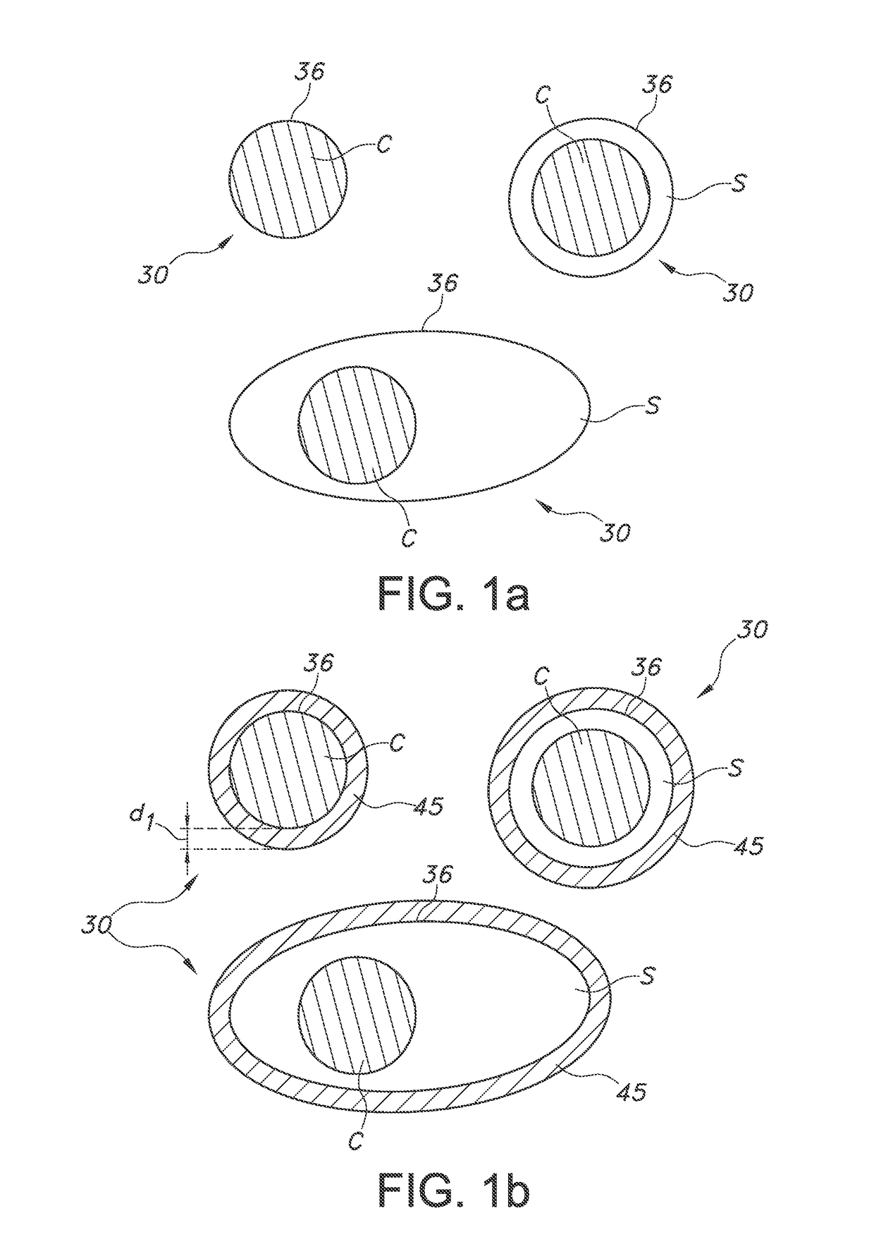
[0004]Quantum dots (qdots or QDs) are currently being studied as phosphors in solid state lighting (SSL) applications (LEDs). They have several advantages such as a tunable emission and a narrow emission band which can help to significantly increase the efficacy of LED based lamps, especially at high CRI. Typically, qdots are supplied in an organic liquid, with the quantum dots surrounded by organic ligands, such as oleate (the anion of oleic acid), which helps to improve the emission efficiency of the dots as well as stabilize them in organic media. The synthesis of silica coatings on quantum dots is known in the art. Koole et al. (in R. Koole, M. van Schooneveld, J. Hilhorst, C. de Mello Donegá, D. 't Hart, A. van Blaaderen, D. Vanmaekelbergh and A. Meijerink, Chem. Mater, 20, p. 2503-2512, 2008) describes experimental evidence in favor of a proposed incorporation mechanism of hydrophobic semiconductor nanocrystals (or quantum dots, QDs) in monodisperse silica spheres (diameter ˜35 nm) by a water-in-oil (W/O) reverse microemulsion synthesis. Fluorescence spectroscopy is used to investigate the rapid ligand exchange that takes place at the QD surface upon addition of the various synthesis reactants. It was

Problems solved by technology

However, silica as grown by the reverse micelle method appears to be relatively porous, making it a less good barrier against oxygen or water than sometimes suggested.
For QDs with organic ligands the stability in ambient conditions is less than in general desired, and it was found that especially water is the root cause for degradation of such QDs.
This may lead to quantum dot based lighting devices which have a quantum efficiency (QE)

Method used


Image

  • Quantum dots in enclosed environment
  • Quantum dots in enclosed environment
  • Quantum dots in enclosed environment

Examples


Example

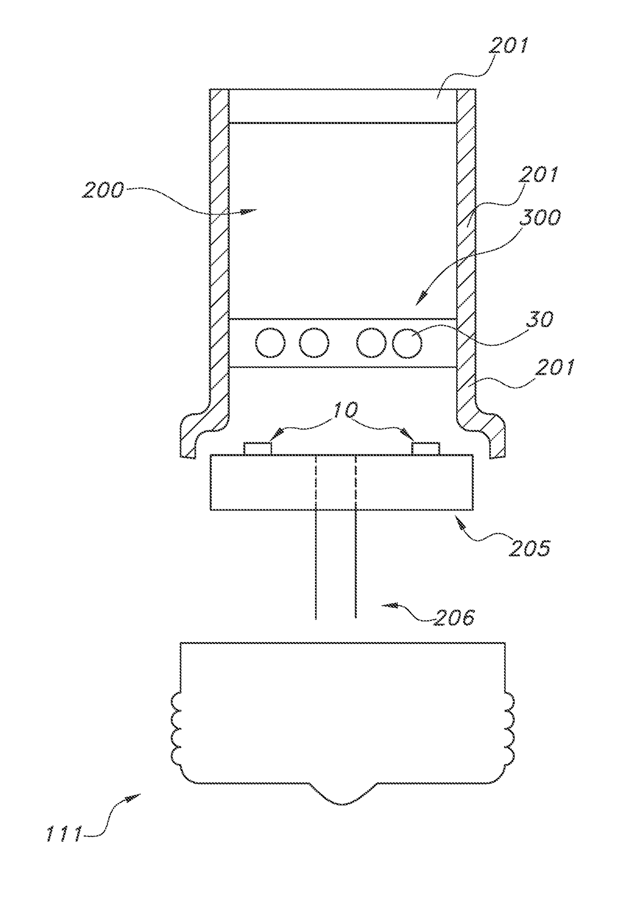
[0083]In a second embodiment, silica coated QDs (peak maximum of ˜610 nm at room temperature) were mixed into commercial silicone. YAG:Ce powder was added to the QD-silicone mixture, and this blend was dispensed into LED packages, after which the phosphor-silicone blend was cured for 2 hours at 150C. The concentration of QDs and YAG:Ce material was tuned in order to achieve a color temperature of 2700 K-3000 K (close to or on the black body line), and high CRI (80, 85, 90, or higher).

Example

[0084]In a third embodiment, LEDs as described in the second embodiment are placed on metal core (MC) PCB's by solder attach, and mounted inside a glass bulb in a process similar to that used to build conventional incandescent light bulbs. The glass bulb allows for hermetic sealing, and prior to sealing the atmosphere within the bulb can be adjusted. Electrical connection to the LED is still possible by metal wires through the glass (as is also done for conventional glass bulbs). Each glass bulb contains 1 LED, and various bulbs were sealed at 950 mbar pressure of air. The relative humidity of the air with which the bulb was filled was varied by using a well-controlled mixture of dry (10 ppmV) and water-saturated air, making use of mass flow controllers. In this way, bulbs were filled with relative humidity's (RH) (at room temperature) of 0% (actually 0.05-0.25%), 1%, 10%, and 80%. The gas content of a few test bulbs was analyzed which confirmed the control over humidity within the ...


PUM


Abstract

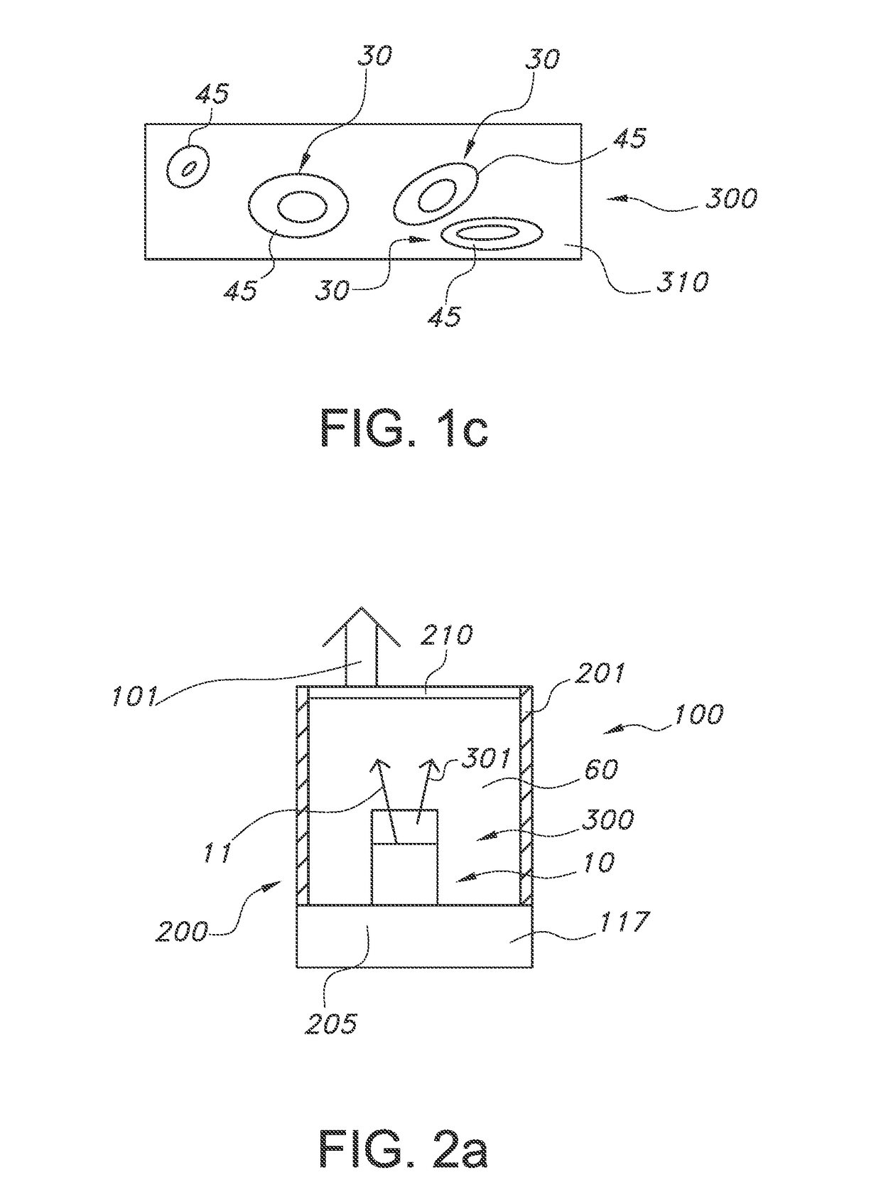
The invention provides a lighting device for providing light, the lighting device comprising a closed chamber with a light transmissive window and a light source configured to provide light source radiation into the chamber, wherein the chamber further encloses a wavelength converter configured to convert at least part of the light source radiation into wavelength converter light, wherein the light transmissive window is transmissive for the wavelength converter light, wherein the wavelength converter comprises luminescent quantum dots which upon excitation with at least part of the light source radiation generate at least part of the wavelength converter light, and wherein the closed chamber comprises a filling gas comprising one or more of helium gas, hydrogen gas, nitrogen gas or oxygen gas, the filling gas having a relative humidity at 19° C. of at least 5%.

Description

FIELD OF THE INVENTION[0001]The invention relates to a lighting device including luminescent nanoparticles. The invention further relates to the production process of such lighting device.BACKGROUND OF THE INVENTION[0002]The sealing of luminescent nanocrystals in lighting devices is known in the art. WO2011 / 053635, for instance, describes a light-emitting diode (LED) device, comprising: (a) a blue-light emitting LED; and (b) a hermetically sealed container comprising a plurality of luminescent nanocrystals, wherein the container is placed with respect to the LED to facilitate down-conversion of the luminescent nanocrystals. Examples of the luminescent nanocrystals include core / shell luminescent nanocrystals comprising CdSe / ZnS, InP / ZnS, PbSe / PbS, CdSe / CdS, CdTe / CdS or CdTe / ZnS. For instance, the luminescent nanocrystals are dispersed in a polymeric matrix.[0003]JP2012009712 describes a light emitting device comprising a semiconductor laser emitting laser light and a light emitting p...

Claims


Application Information

Patent Timeline
IPC IPC(8): F21K9/64F21K9/232F21V31/00F21V9/16F21V29/70
CPCF21K9/64F21V9/16F21Y2115/10F21V31/00F21K9/232F21V29/70F21K9/23F21Y2101/00F21V9/32F21V9/45F21V9/08
Inventor KOOLE, ROELOFVELDMAN, DIRKBOHMER, MARCEL RENESHIMIZU, KENTAROKOOPMANS, LOES JOHANNA MATHILDATIMMERING, CORNELIS EUSTATIUS
Owner LUMILEDS
Why Eureka
Try Eureka