Electromechanical strut with integrated flex coupling and slip device and clutch/coupling assembly therefor

a technology of flex coupling and flex coupling, which is applied in the direction of slip coupling, doors, gearing, etc., can solve the problems of increasing the effort required, manual opening or closing a lift gate can be inconvenient for some users, and achieve the effect of facilitating slip between the motor and the stru

Active Publication Date: 2015-12-31
MAGNA CLOSURES INC
View PDF8 Cites 45 Cited by
  • Summary
  • Abstract
  • Description
  • Claims
  • Application Information

AI Technical Summary

Benefits of technology

The present disclosure describes an electromechanical strut for use in a powered closure system of a motor vehicle. The strut includes a housing, an electric motor, a power screw, and a clutch / coupling assembly. The clutch / coupling assembly integrates a slip clutch device and a flexible drive coupling, which allows for axial misalignment between the motor gear-assembly and the power screw. The clutch / coupling assembly acts as a common assembly for both the motor and the power screw, providing a torque limiting function, a shock damping function, and a misalignment accommodating function. The clutch / coupling assembly is compact and allows for a lower torque motor to be used, reducing the diameter of the housing. The technical effects of the invention include a compact arrangement of the electromechanical strut, improved torque limiting, shock damping, and misalignment accommodating functions.

Problems solved by technology

Depending on the size and weight of the lift gate, this effort can be difficult for some users.
Additionally, manually opening or closing a lift gate can b e inconvenient, particularly when the user's hands are full.
However, the gas struts also hinder efforts to close the lift gate, as the struts re-pressurize upon closing, increasing the effort required.
Furthermore, the use of gas struts still requires that the lift gate is manually opened and closed.
However, the power actuator described in the '567 patent is not without its disadvantages.
The power actuator is comprised of multiple parts, each of which needs to be assembled and mounted to the vehicle separately, increasing costs.
Due to the limited space available, the motor is small and requires the assistance of the gas strut.
However, these devices can increase the cost and complexity of powered actuators as well as impact the available packaging requirements.

Method used


Image

  • Electromechanical strut with integrated flex coupling and slip device and clutch/coupling assembly therefor
  • Electromechanical strut with integrated flex coupling and slip device and clutch/coupling assembly therefor
  • Electromechanical strut with integrated flex coupling and slip device and clutch/coupling assembly therefor

Examples


Embodiment Construction

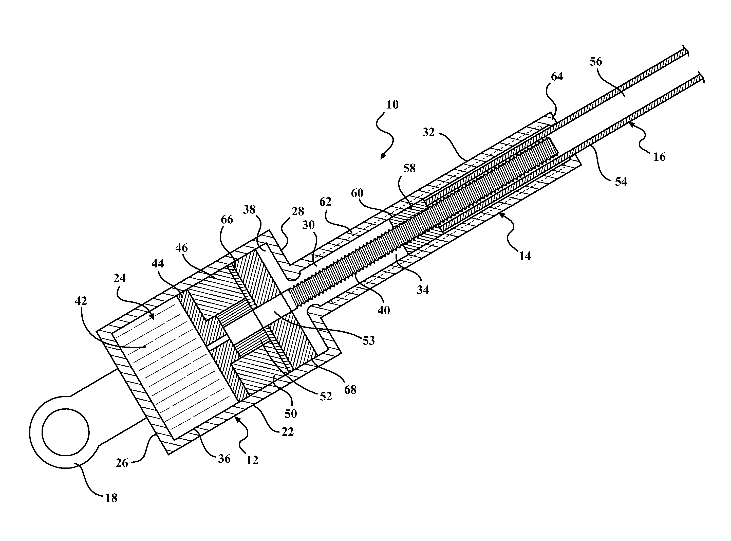
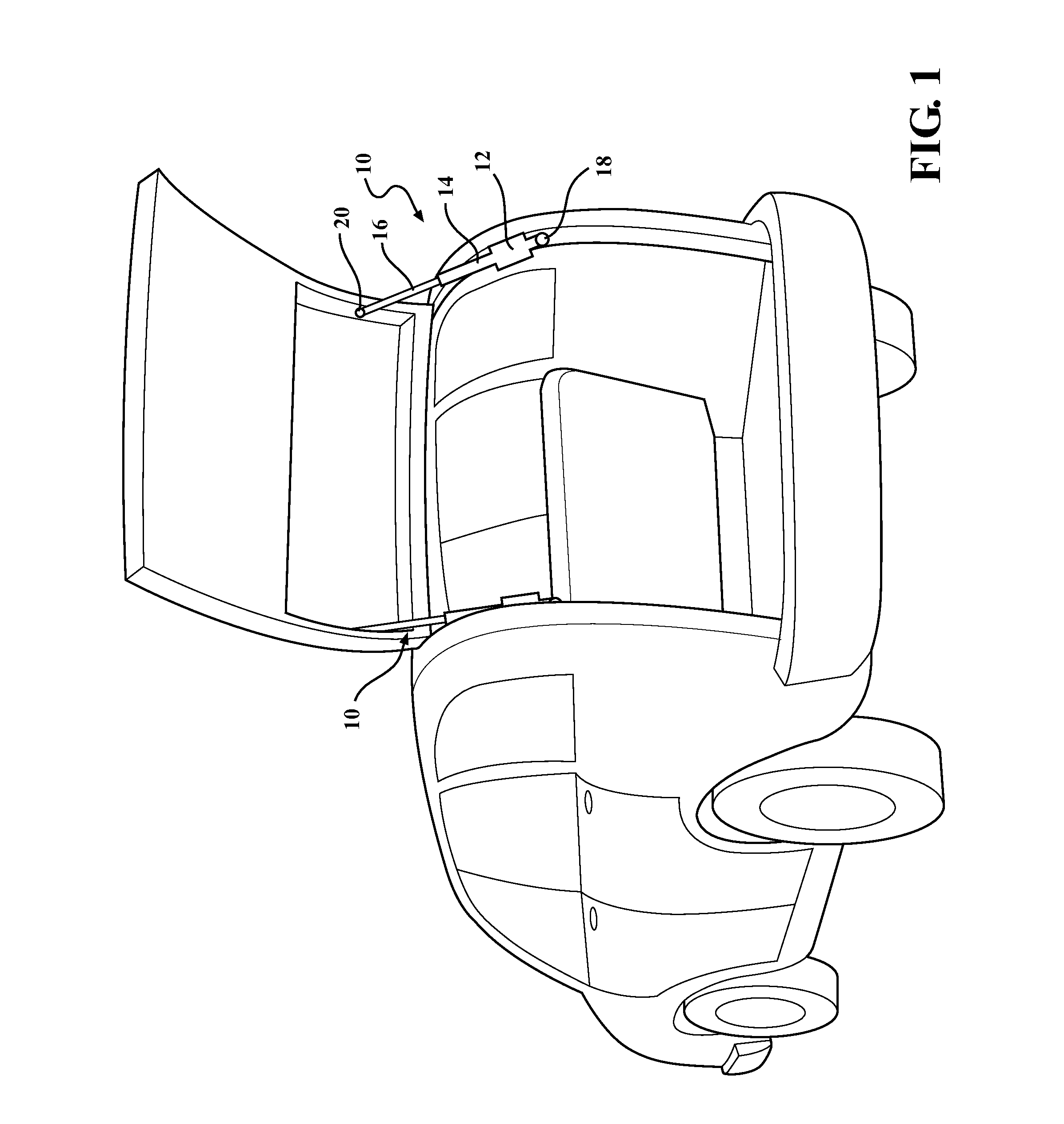
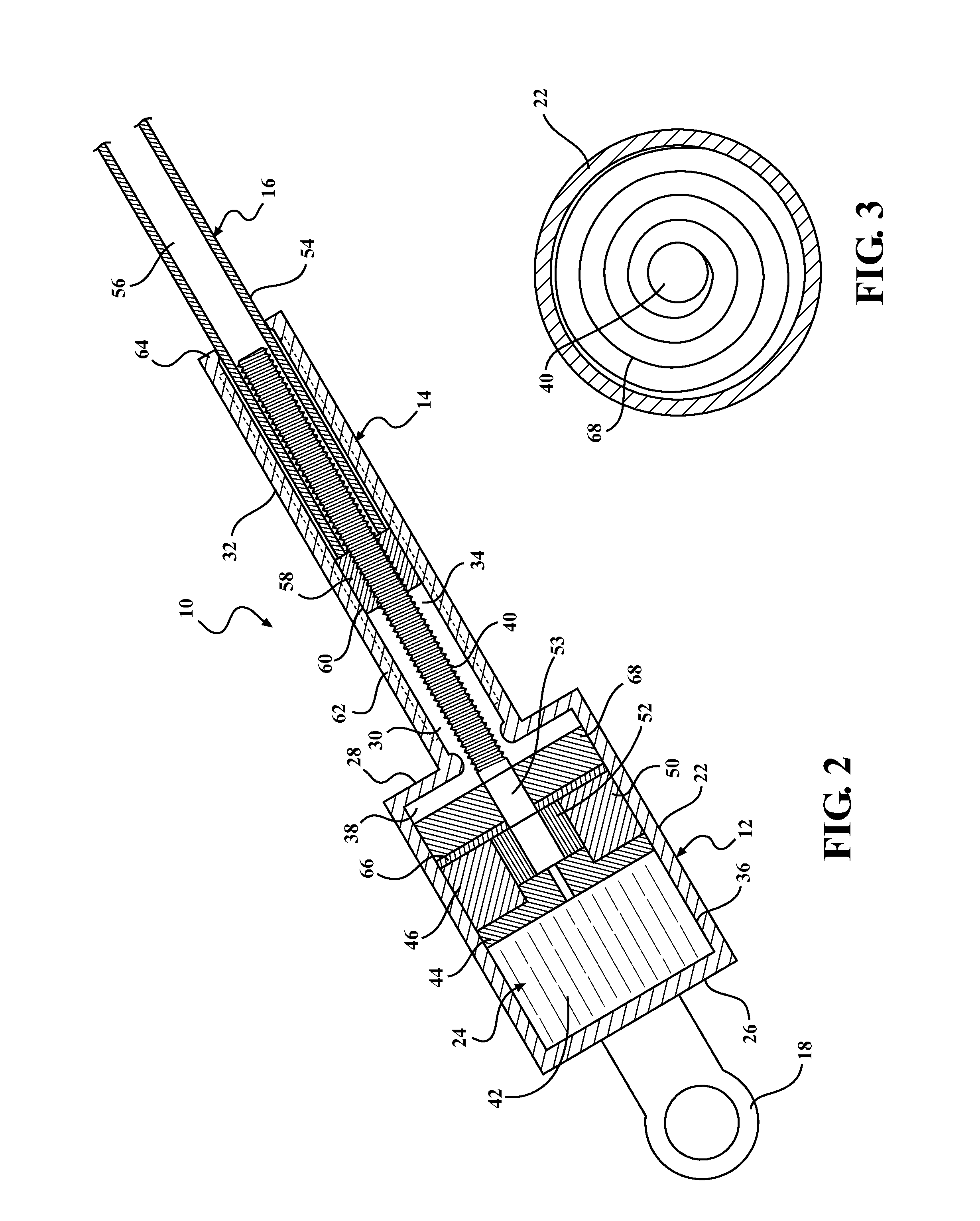
[0056]Vehicles, particularly passenger vehicles, are equipped with numerous moveable closure panels for providing openings and access within and through defined portions of the vehicle body. To enhance operator convenience, many vehicles are now equipped with power-operated closure systems to automatically control movement of all types of closure panels including, without limitation, hatch lift gates, trunk and hood deck lids, sliding and hinged doors, sun roofs and the like. The powered mechanical advantage is often provided by an electromechanical drive device including, without limitation, motor driven gear drives, cable drives, chain drives, belt drives and power screw drives. Current development focus is largely directed to improving these popular systems through weight and part count reduction, packaging efficiency, system noise, back drive effort, cost and ease of assembly and service repair. Accordingly, the present disclosure addresses all of these issues.

[0057]For purposes...


PUM


Abstract

An electromechanical strut is provided for moving a pivotal closure member between an open position and a closed position relative to a motor vehicle body. The electromechanical strut includes a housing connected to one of the closure member and the motor vehicle body. An extensible shaft is connected to the other of the closure member and the motor vehicle body for slidable movement relative to the housing. A motor-gear assembly operably drives a rotatable power screw. A drive mechanism converts rotary motion of the power screw into linear motion of the extensible shaft to move the extensible shaft between a retracted position corresponding to the closed position of the closure member and an extended position corresponding to the open position of the closure member. A clutch / coupling assembly is operably disposed between the motor-gear assembly and the power screw and integrates a slip clutch device and a flexible coupling into a common unit.

Description

CROSS-REFERENCE TO RELATED APPLICATIONS[0001]This application claims the benefit of U.S. Provisional Application Ser. No. 62 / 018,102, filed Jun. 27, 2014, and the benefit of U.S. Provisional Application Ser. No. 62 / 024,736, filed Jul. 15, 2014, both of which are incorporated herein by reference in their entirety.FIELD OF THE INVENTION[0002]The present disclosure relates to an electrically-driven mechanical strut. More particularly, the present disclosure relates to an electromechanical strut used to raise or lower an automotive lift gate.BACKGROUND OF THE INVENTION[0003]This section provides background information which is not necessarily prior art to the inventive concepts associated with the present disclosure.[0004]Lift gates provide a convenient access to the cargo areas of hatchbacks, wagons, and other utility vehicles. Typically, the lift gate is hand operated, requiring manual effort to move the lift gate between the open and the closed positions. Depending on the size and we...

Claims


Application Information

Patent Timeline
Patent Type & Authority Applications(United States)
IPC IPC(8): E05F15/622F16H25/24F16D43/21B60J5/10F16H25/20
CPCE05F15/622F16D43/21F16H25/24E05Y2201/216F16D41/064E05Y2900/546F16H2025/2087F16H2025/2071E05Y2201/236F16D3/06F16D3/12F16D3/58F16D7/002F16D7/06F16D2300/22F16D43/204
Inventor SCHEURING, JOSEPHNOWICKI, WIESLAW
Owner MAGNA CLOSURES INC
Why Eureka
Try Eureka