Cooling device for multiple cylinder engine

a cooling device and engine technology, applied in the direction of engine cooling apparatus, liquid cooling, cylinders, etc., can solve the problems of deteriorating engine fuel efficiency, affecting the fuel efficiency of the engine, and generating temperature differences between the cylinders, so as to achieve the effect of suppressing the temperature difference between the upper and lower sides of the cylinders and suppressing the temperature difference between the intake side and the exhaust side of the cylinders

Active Publication Date: 2015-12-31
MAZDA MOTOR CORP
View PDF8 Cites 37 Cited by
  • Summary
  • Abstract
  • Description
  • Claims
  • Application Information

AI Technical Summary

Benefits of technology

[0021]The invention according to the present application can obtain the following effects by the above configuration.
[0022]According to the above cooling device, the passage cross-sectional area of the cylinder axis direction upper side (cylinder head side) of the exhaust-side portion of the water jacket of the cylinder block is larger than the passage cross-sectional area of the cylinder axis direction lower side of the exhaust-side portion of the water jacket of the cylinder block. Therefore, an exhaust side upper portion of the cylinder block can be cooled down more than an exhaust side lower portion of the cylinder block, the exhaust side upper portion being a portion which especially tends to increase in temperature due to the exhaust gas when the engine is actually operating. On this account, the temperature difference between the upper side and lower side of each cylinder can be suppressed.
[0023]With the restrictor portion provided in the vicinity of the introducing portion, the cooling liquid introduced from the introducing portion is restricted from flowing to the intake-side portion of the water jacket of the cylinder block. Therefore, by supplying a larger amount of cooling water to the exhaust-side portion, the cylinder block at the exhaust side which tends to become higher in temperature than the intake side can be cooled down. Thus, the temperature difference between the intake side and exhaust side of each cylinder can be suppressed.
[0024]Further, the introducing portion through which the cooling liquid is introduced to the water jacket of the cylinder block is provided at the first side of the cylinder row. The restrictor portion, which restricts the cooling liquid introduced through the introducing portion from flowing to the intake-side portion of the water jacket of the cylinder block, is provided in the vicinity of the introducing portion. The discharging portion through which the co

Problems solved by technology

Thus, a temperature difference among the cylinders tends to be generated.
When temperature distribution in each cylinder becomes non-uniform due to the temperature difference between the upper side and lower side of each cylinder and the temperature difference between the intake side and exhaust side of each cylinder, roundness of each cylinder bore deteriorates due to heat deformation.
Therefore, sliding resistance at the cylinder bore due to sliding of a piston ring increases, and this deteriorates the fuel efficiency of the engine.
Further, the following problems may occur.
Specifically, a large amount of air-fuel mixture may leak into a crank case and the like through an expanded gap between the piston and the cylinder, and this may accelerate the deterioration of engine oil and the corrosion of metal.
In addition, lubricating oil may flow into a combustion chamber, and this may cause an increase in oil consumption.
Due to the temperature difference among the cylinders, thermal distortion of the entire engine occurs.
With this, the roundness of each cylinder bore deteriorates as described above, or uniformity of intake air filling by an intake s

Method used


Image

  • Cooling device for multiple cylinder engine
  • Cooling device for multiple cylinder engine
  • Cooling device for multiple cylinder engine

Examples


Embodiment Construction

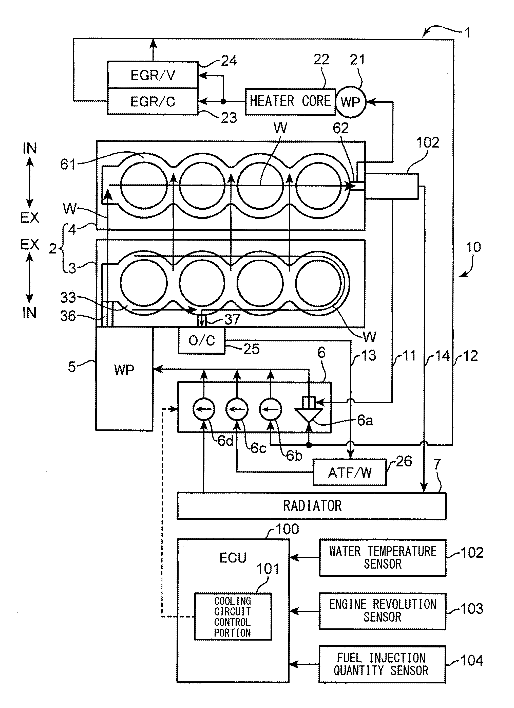
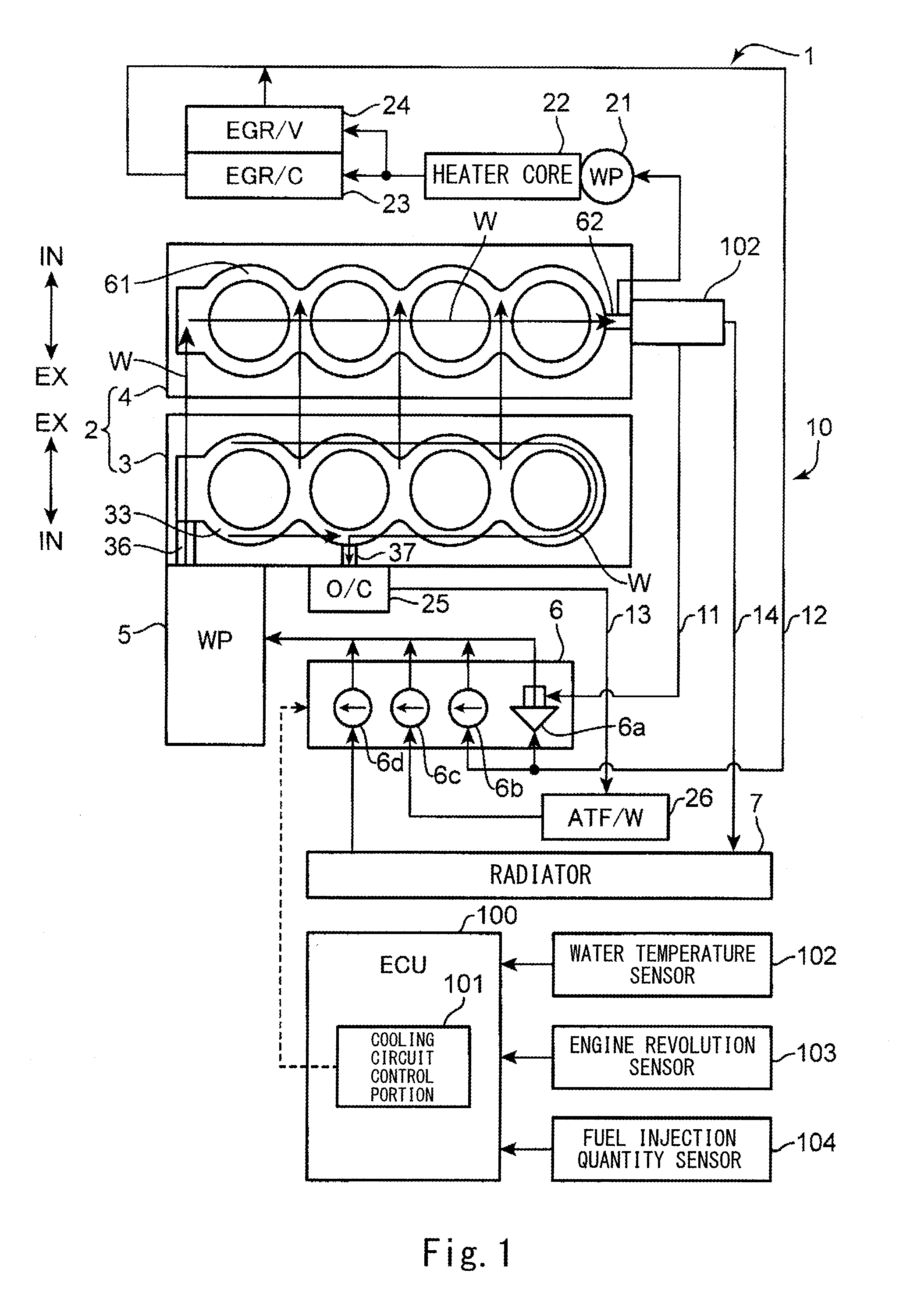
[0049]Hereinafter, an embodiment of a cooling device for a multiple cylinder engine according to the present invention will be explained in reference to FIGS. 1 to 15.

[0050]FIG. 1 shows a schematic configuration of a cooling device 1 for the multiple cylinder engine according to the embodiment of the present invention. A multiple cylinder engine 2 (hereinafter simply referred to as an “engine”) is a so-called cross-flow type in-line four-cylinder diesel engine in which: four cylinders are arranged in series in a crank shaft direction; and an intake system and an exhaust system are arranged at respective opposing sides of a cylinder head 4. The engine 2 is mounted in an engine room (not shown) provided at a vehicle front portion such that: a cylinder row extends in a vehicle width direction; the exhaust system is located at a rear side in a vehicle front / rear direction; and a cylinder axis of each cylinder extends in an upper / lower direction.

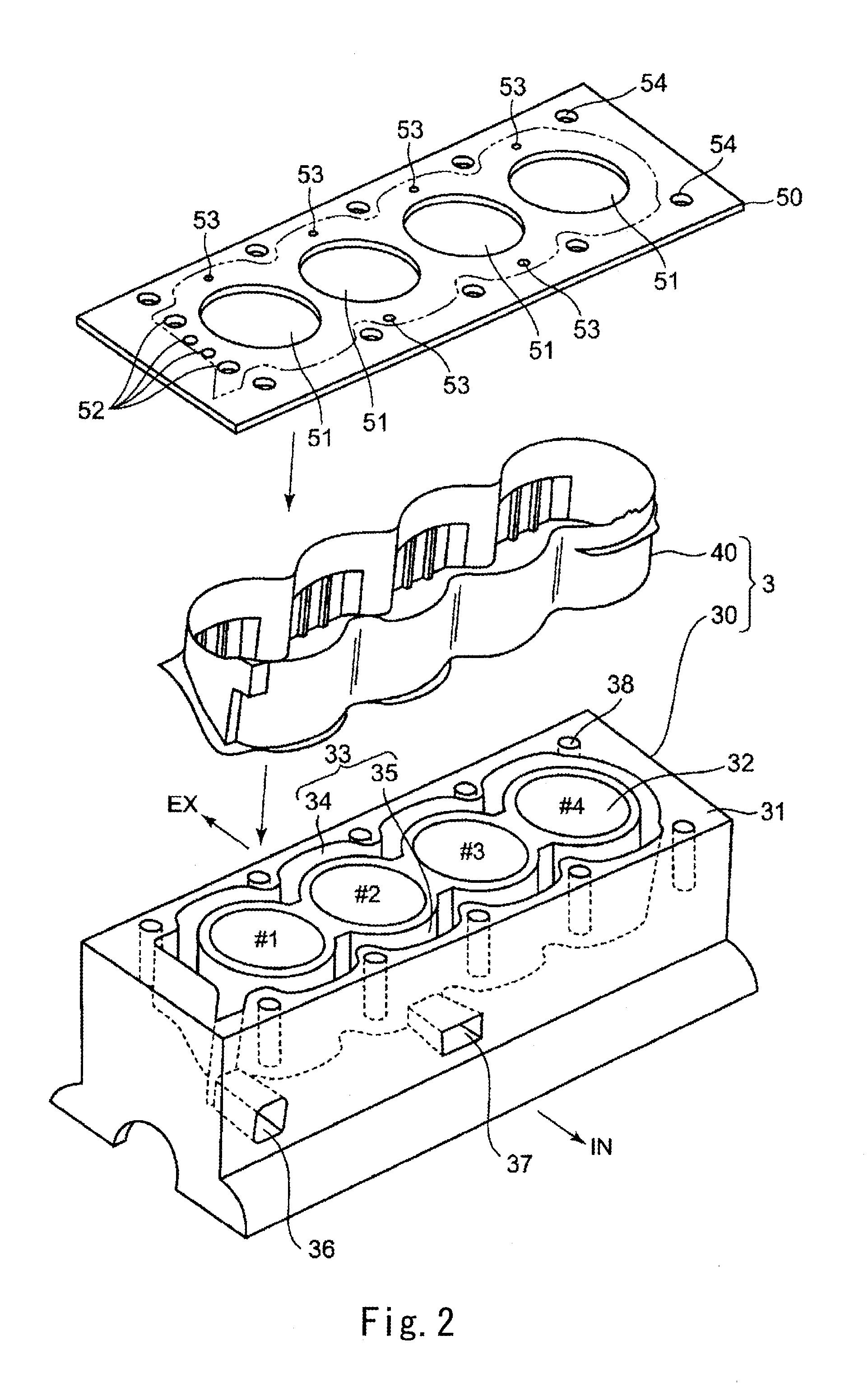
[0051]The engine 2 is mainly constituted b...


PUM


Abstract

The present invention is configured such that: a cylinder block includes an introducing portion provided at a first side of a cylinder row, cooling liquid being introduced through the introducing portion to a water jacket, a restrictor portion provided in a vicinity of the introducing portion and configured to restrict the cooling liquid, introduced through the introducing portion, from flowing to an intake-side portion of the water jacket, and a discharging portion provided at a middle portion of the cylinder row at an intake side, the cooling liquid being discharged from the water jacket through the discharging portion; and an exhaust-side portion of the water jacket is formed such that a passage cross-sectional area of a cylinder axis direction upper side of the exhaust-side portion is larger than the passage cross-sectional area of a cylinder axis direction lower side of the exhaust-side portion.

Description

TECHNICAL FIELD[0001]The present invention relates to a cooling device for a multiple cylinder engine of a car or the like, and particularly belongs to a technical field of an engine in which a cylinder head and a cylinder block are cooled down by a cooling liquid.BACKGROUND ART[0002]To improve fuel efficiency and exhaust emission control performance, cars and the like conventionally adopt a technology for quickly warming up an engine when the engine is cold.[0003]For example, PTL 1 discloses a technology for quickly completing the warm-up in such a manner that: when the engine is cold, the flow of a cooling liquid to a cylinder block is blocked, but a small amount of cooling liquid is supplied to a cylinder head from one end of a cylinder row toward the other end of the cylinder row; as the temperature of the cooling liquid increases, the cooling liquid is supplied to the cylinder block from one the end of the cylinder row to the other end of the cylinder row; and the flow rate of ...

Claims


Application Information

Patent Timeline
IPC IPC(8): F01P3/02F02F1/14F02F1/40F01P3/20F01P5/10
CPCF02F1/14F01P2003/028F01P2060/16F01P5/10F01P2060/00F02F1/10F01P3/02F01P3/20F01P2003/021F01P2003/027F01P2003/024F02F1/40
Inventor MATSUMOTO, DAISUKETABATA, DAISUKENAITO, MASAHIRO
Owner MAZDA MOTOR CORP
Why Eureka
Try Eureka