Vehicle lighting device

a technology for vehicle lighting and support devices, which is applied in fixed installation, lighting and heating apparatus, and support devices for lighting, etc., can solve the problems of limited number, inability to quickly and finely adjust the light shape, and inability to achieve dynamic adjustment of the light shape based on the position of the vehicle coming in the opposite direction

Inactive Publication Date: 2015-12-31
CORETRONIC
View PDF7 Cites 19 Cited by
  • Summary
  • Abstract
  • Description
  • Claims
  • Application Information

AI Technical Summary

Benefits of technology

[0022]In an embodiment of the invention, the control unit determines whether the vehicle coming from the opposite direction exists and a relative distance between the vehicle coming from the opposite direction and the sensing unit according to the signal having the image information or the position information related to the vehicle coming from the opposite direction, and the control unit controls the light valve to adjust the light distribution pattern of the illumination beam when determining that the vehicle coming from the opposite direction exists in the front.
[0023]In an embodiment of the invention, the control unit is electronically connected to the light source module, and when the humidity information reaches a predetermined value, the control unit controls the light source module to adjust the color temperature of the illumination beam.
[0024]In an embodiment of the invention, the illumination beam is provided by a light source module, and the light valve includes a digital micro-mirror device. The digital micro-mirror device includes a plurality of micro-mirrors, each of the micro-mirrors is capable of oscillating independently and is capable of being switched to different states, the different states of the micro-mirrors correspond to different oscillating angles, the states of the micro-mirrors are controlled to control a reflecting direction that the illumination beam irradiates each of the micro-mirrors, such that the digital micro-mirror device adjusts the light distribution pattern of at least a portion of the illumination beam through the micro-mirrors.

Problems solved by technology

Therefore, limited by the number of the light sources, quick and fine adjustment of the light shape cannot be achieved, or dynamic adjustment of the light shape based on a position of the vehicle coming in the opposite direction cannot be achieved.

Method used


Image

  • Vehicle lighting device
  • Vehicle lighting device
  • Vehicle lighting device

Examples


Embodiment Construction

[0041]The present invention will now be described more fully with reference to the accompanying drawings, in which exemplary embodiments of the invention are shown. The terms used herein such as “above”, “below”, “front”, “back”, “left” and “right” are for the purpose of describing directions in the figures only and are not intended to be limiting of the invention.

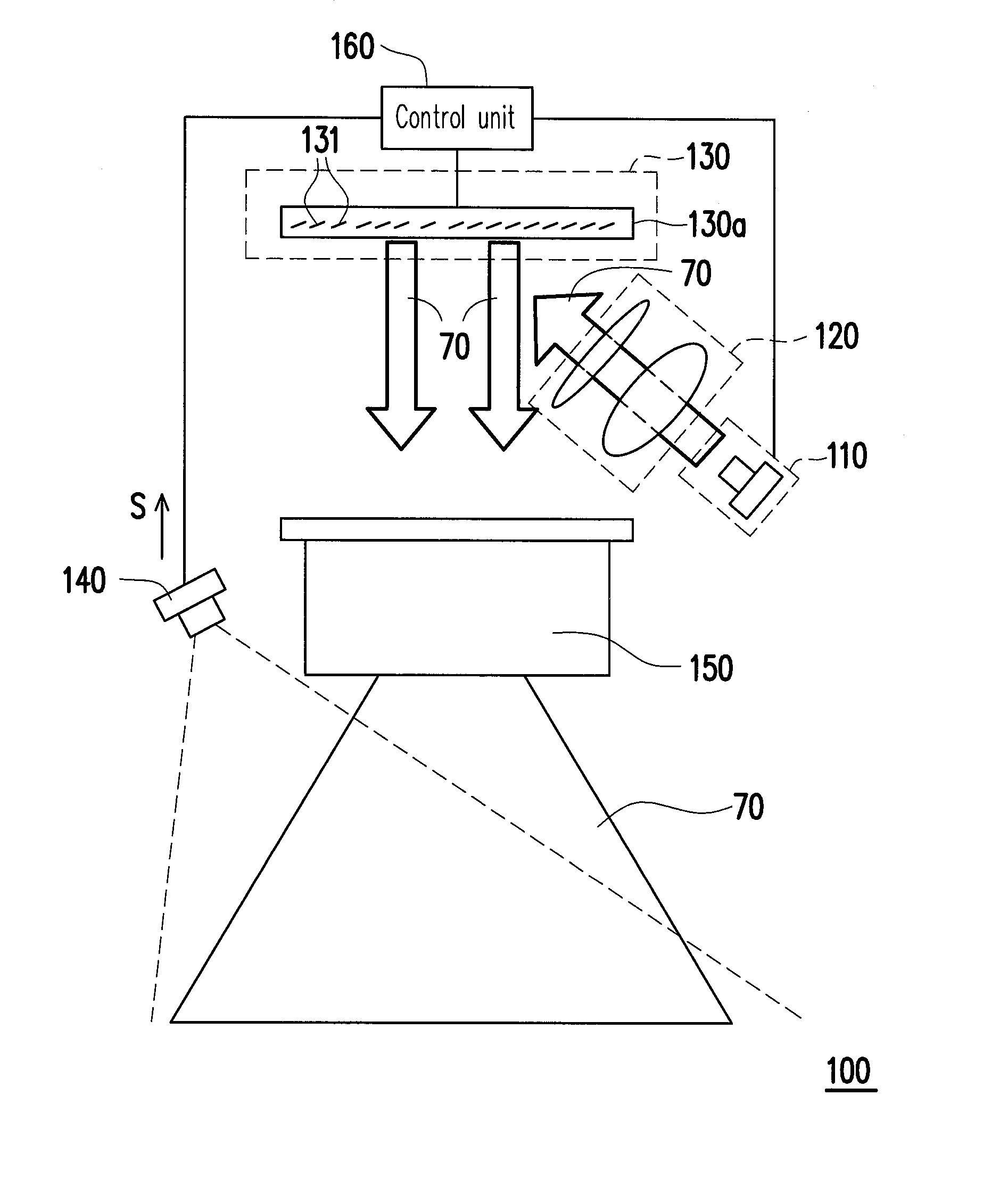
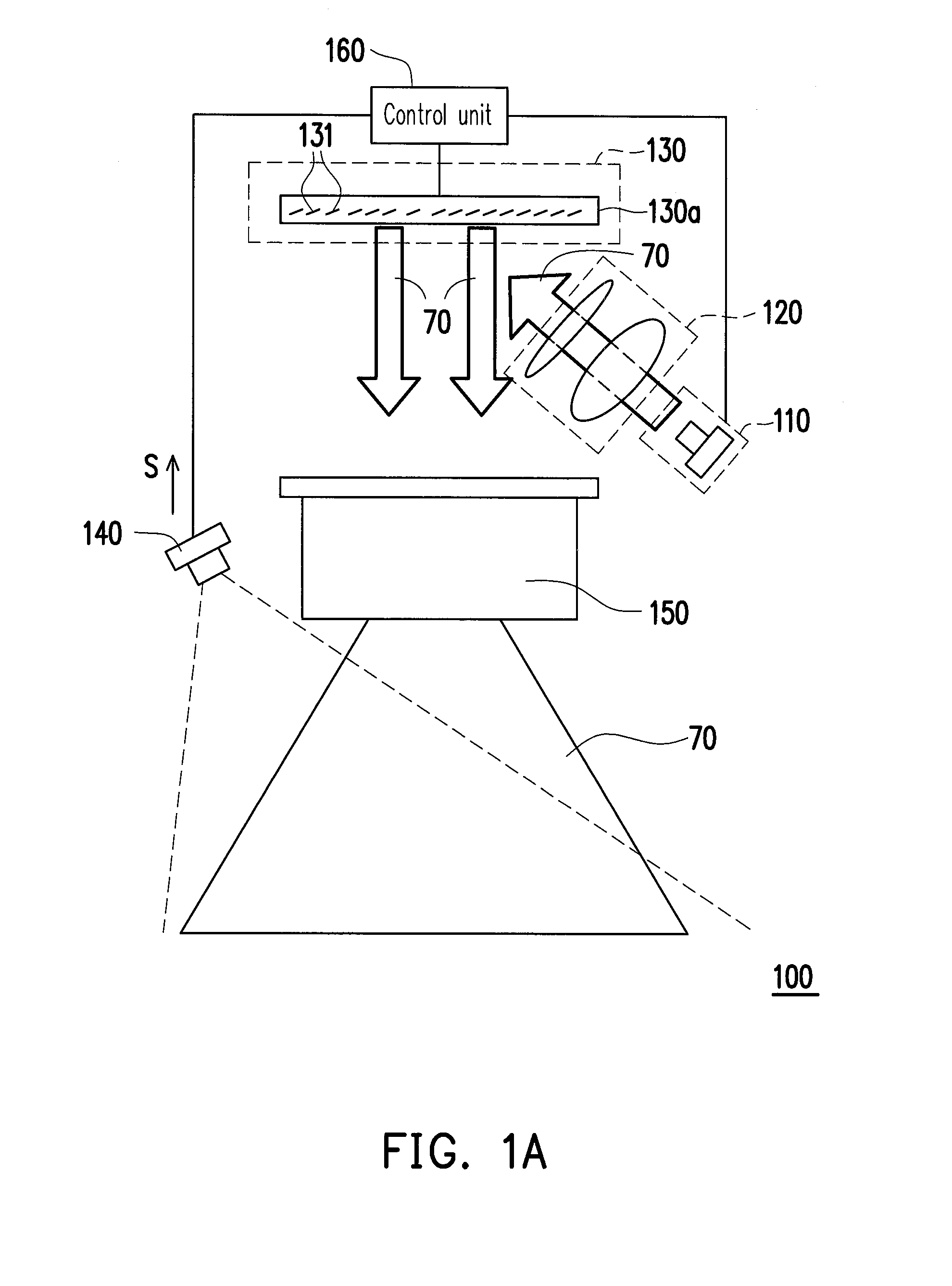
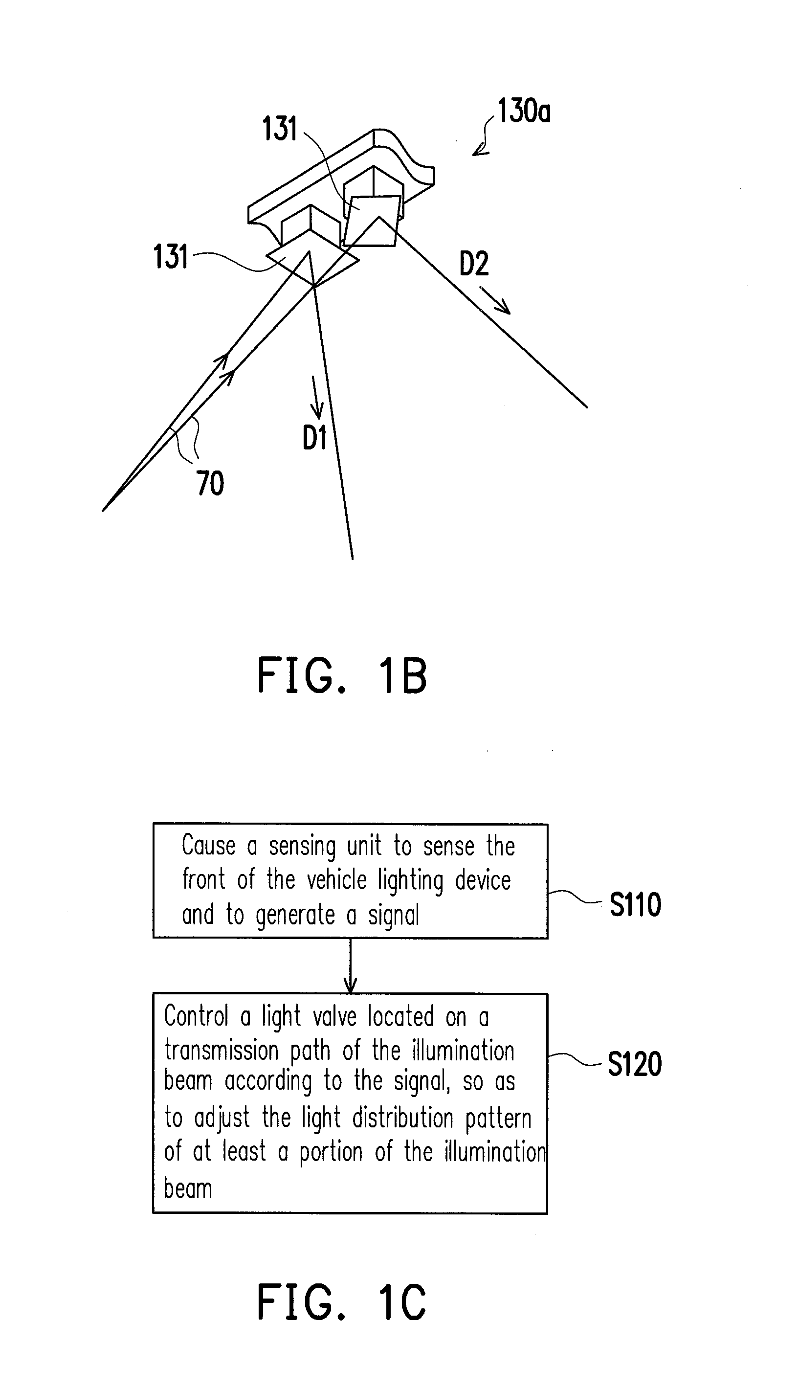
[0042]FIG. 1A is a structural schematic diagram of a vehicle lighting device according to an embodiment of the invention. FIG. 1B is a schematic diagram of two micro-mirrors of a digital micro-mirror device of FIG. 1A in different states. Referring to FIG. 1A, the vehicle lighting device 100 includes a light source module 110, a relay lens set 120, a light valve 130, a sensing unit 140, a projection lens set 150 and a control unit 160. The light valve 130 is defined as an optical element controlling a beam reflecting direction or an optical element that allows the beam to pass there through or blocks the beam, which is kno...


PUM


Abstract

A vehicle lighting device including a light source module, a light valve, a sensing unit, a projection lens set and a control unit. The light source module provides an illumination beam. The light valve is located on a transmission path of the illumination beam, and is capable of being switched to different states for adjusting the illumination beam. The sensing unit senses the front of the vehicle lighting device and generates a signal. The projection lens set is disposed on an optical path of the illumination beam for projecting at least a portion of the illumination beam. The control unit is electrically connected to the light valve and the sensing unit for receiving the signal. The control unit controls the light valve to adjust a light distribution pattern of the illumination beam according to the signal, and project the illumination beam to the front through the projection lens set.

Description

CROSS-REFERENCE TO RELATED APPLICATION[0001]This application claims the priority benefit of Chinese application serial no. 201410295591.X, filed on Jun. 26, 2014. The entirety of the above-mentioned patent application is hereby incorporated by reference herein and made a part of this specification.BACKGROUND[0002]1. Technical Field[0003]The invention relates to a lighting device, and particularly relates to a vehicle lighting device.[0004]2. Related Art[0005]Recently, vehicle front lights composed of solid-state light sources such as light-emitting diodes (LEDs) and laser diodes gradually occupy a space in the market. A light-emitting efficiency of the LED is approximately between 5%-8%, and the LEDs have different color temperatures and an excellent power-saving effect. On the other hand, since the laser diode has a light-emitting efficiency of about 20% higher, in order to break through the limitation of the luminous efficiency of the LED, an applicable and high-efficiency light s...

Claims


Application Information

Patent Timeline
Patent Type & Authority Applications(United States)
IPC IPC(8): F21S8/10B60Q1/08F21W107/10
CPCB60Q1/143B60Q2300/056F21S41/675F21S41/25B60Q2300/42
Inventor CHUANG, FU-MINGLIAO, CHIEN-CHUNG
Owner CORETRONIC
Why Eureka
Try Eureka