System and method for scanning a surface and computer program implementing the method

a scanning system and surface technology, applied in the field of scanning systems, can solve the problems of limiting the amount of images which can be measured per second, negatively affecting the distance of detection, and sacrificing spatial performance, so as to increase the distance of emission and achieve the effect of sacrificing spatiality

Active Publication Date: 2015-12-31
UNIV POLITECNICA DE CATALUNYA
View PDF0 Cites 206 Cited by
  • Summary
  • Abstract
  • Description
  • Claims
  • Application Information

AI Technical Summary

Benefits of technology

[0089]According to another embodiment, the method of the second aspect of the invention comprises determining and varying the degree of divergence of the light beam and/or varying the number of light redirection elements of each sub-model, in an automatic manner and/or under a user's indication and/or according to a series of local input signals and/or remote input signal...

Problems solved by technology

Taking into account that one of the main factors that sets the limitation in the capability of measuring in distance in LIDAR systems is the capability of detecting low power reflected optical beams, the effect of energy concentration of the sequential scanning systems successfully maximizes the measurable distance as a result of harnessing all the optical power available for a single point of measurement.
This limits the amount of images which can be measured per second.
This has an impact on the light energy received in each point of the surface and, accordingly, negatively affects the distance of detection given that the illumination energy is divided among all the points of the surface.
A sequential scanning system would require less illumination energy but its performance in terms of measurement speed would also be limited, being able to have limitations in moving object measurement.
In systems based on arrays of detectors, this effect can be acceptable for short distances (10 to 15 m) where the illumination intensity per m2 remains high, but when measurement of medium-long distances (more than 15 m) and large areas is required, this phenomenon becomes a problem, since the illumination ...

Method used


Image

  • System and method for scanning a surface and computer program implementing the method
  • System and method for scanning a surface and computer program implementing the method
  • System and method for scanning a surface and computer program implementing the method

Examples


Embodiment Construction

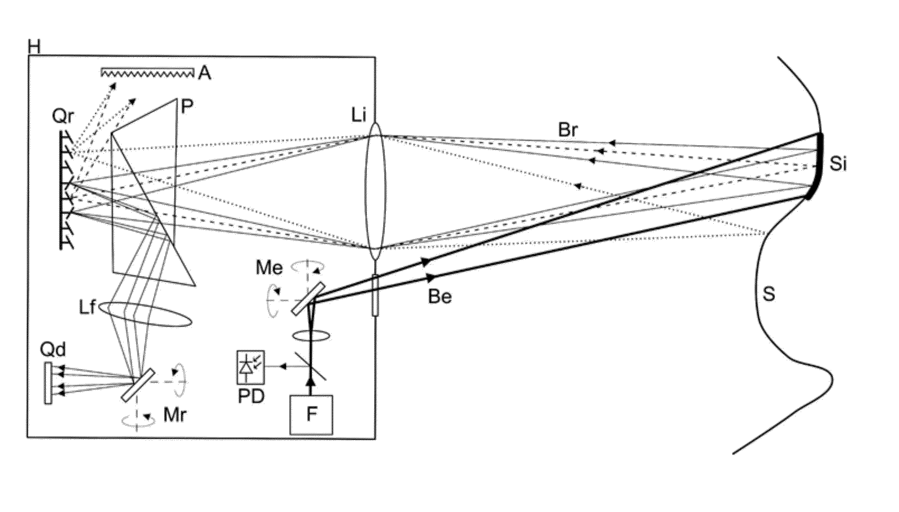
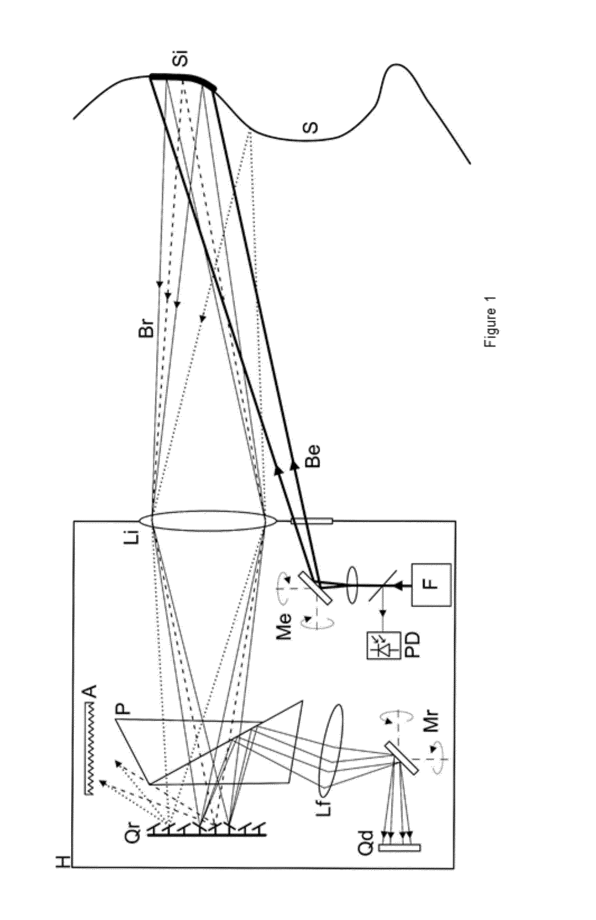
[0105]FIG. 1 illustrates part of the system proposed by the first aspect of the invention for one embodiment for which it comprises, arranged in a casing H:[0106]illumination means including a light source F, generally laser, and a series of optical elements arranged at the outlet of the light source F (beam splitter and lenses), as well as a photodetector PD for detecting the pulse emitted by the light source F and generating a corresponding detection signal to be used as the start of time counting for a pulsed TOF system. The illumination means are configured and arranged for projecting on the surface to be scanned S a light beam Be with a determined divergence for illuminating a sub-area Si of the area forming the surface to be scanned S;[0107]light direction means associated with the illumination means configured for directing the light beam Be so that it illuminates different sub-areas Si of the surface to be scanned S in an alternating manner, and comprising a reflective and / o...


PUM


Abstract

A system and method for scanning a surface and a computer program implementing the method. The method is suitable for performing the functions carried out by the system of the invention. The computer program implements the method of the invention. The system
    • means for illuminating illuminates different sub-areas (Si) of a surface (S) with a light beam (Be) in an alternating manner, and
    • receives and detects the portions of reflected light (Br) reflected on same, including:
    • one or more light detectors (D); and
    • light redirection means including a determined spatial distribution model (Qr) of the light redirection elements (GM), which receive the portions of reflected light (Br) and sequentially redirect them towards the light detector or detectors (D).

Description

FIELD OF THE ART[0001]The present invention relates generally, in a first aspect, to a system for scanning a surface, comprising means for illuminating different regions of a surface to be scanned and means for receiving and detecting the portions of light reflected on same including one or more light detectors, and more particularly to a system which allows using the total spatial resolution of the light detector or detectors for each of the regions of the surface to be scanned.[0002]A second aspect of the invention relates to a method suitable for performing the functions carried out by the system of the first aspect.[0003]A third aspect of the invention relates to a computer program implementing the method of the second aspect.BACKGROUND OF THE INVENTION[0004]TOF (acronym of “Time Of Flight”), LIDAR (acronym of “Light detection and ranging”) or LADAR (acronym of “Laser detection and ranging”) measurement systems are systems which allow measuring distances by means of using a ligh...

Claims


Application Information

Patent Timeline
IPC IPC(8): G01S17/89G01S17/32G01S7/481G01S17/66G01S17/931
CPCG01S7/4817G01S17/89G01S17/936G01S17/66G01S17/32G01S17/931
Inventor ROYO ROYO, SANTIAGORIUS GRAS, JORDI
Owner UNIV POLITECNICA DE CATALUNYA
Why Eureka
Try Eureka