Support structures for a flexible electronic component

Active Publication Date: 2015-12-31
FLEXTERRA INC
View PDF2 Cites 181 Cited by
  • Summary
  • Abstract
  • Description
  • Claims
  • Application Information

AI Technical Summary

Benefits of technology

[0024]In one case, the processor, which may be a generally purpose micro-processor type of controller or a special purpose controller, the battery, the battery charger unit, the computer readable memory and the communications module may be integrated within, for example, an endpiece or a side wall of the attachable article or in a separate rigid module, and these components may be sealed or otherwise protected from water, air, dirt, etc. to which the exterior of the device is exposed. Any or all of these electronic components may be encapsulated in a hermetically sealed manner to prevent any direct exposure of these components to exterior forces and environmental hazards.
[0025]Still further, the flexible support of the attachable article may incorporate various types of structure to protect the flexible display by, for example, limiting the possible types of motion that the flexible display can undergo. These types of structures can, for example, include a set of transverse bars, stays or stints disposed in or on the flexible support to limit the torsional motion of the flexible support to thereby prevent damage to the flexible display due to torsional bending of the flexible display. In a similar manner one or more longitudinal m

Problems solved by technology

However, unfortunately, typical mobile devices such as smart phones have electronic displays that are flat and rigid in nature.
Thus, while these displays are useful in implementing many different applications, the device on which the display is present must still typically be held in a hand, or must be stored in a pocket, a purse, a briefcase or other container, which makes the electronic device less accessible in many situations, such as when a person is carrying other items, undertaking an athletic activity such as running, walking, etc.
Moreover, in many cases these traditional electronic devices require two free hands to hold and operate, making these devices cumbersome or difficult to use or to view in situations in which, for example, a person has only one or no free hands or is otherwise occupied.
While flexible displays are generally known and are starting to come into more common usage, flexible displays have not been widely incorporated into easily portable items such as items of clothing, wristbands, jewelry, etc., or on items that are easily attached to other items, much less in a manner that makes the display more useable and visible to the user in many different scenarios.
The strain profile created by the curvature of bending of the component, as well as any built-in strains that may exist within the component, may, in turn, cause one or more of the layers of the flexible electronic component to buckle, crack, or otherwise become damaged.
The brittle, inorganic layers in a flexible electronic component can, however, only typically withstand strains of approximately 1% before buckling or cracking, depending of course on the processing conditions of the component.
As such, the brittle layers of the flexible electronic component generally buckle or crack firs

Method used


Image

  • Support structures for a flexible electronic component
  • Support structures for a flexible electronic component
  • Support structures for a flexible electronic component

Examples


Embodiment Construction

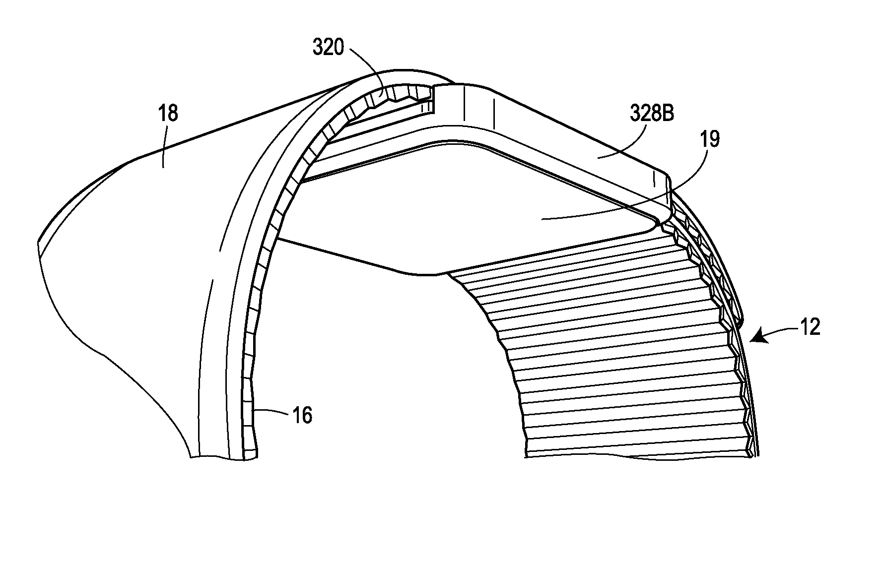
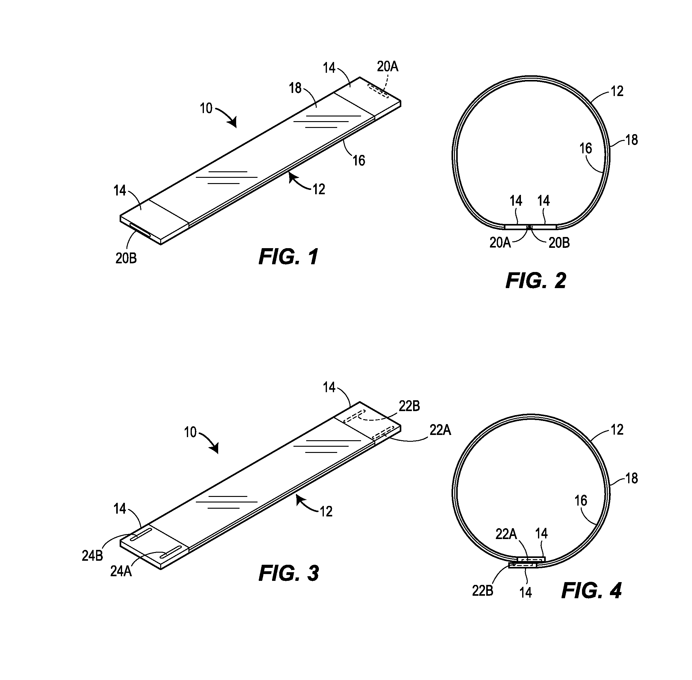
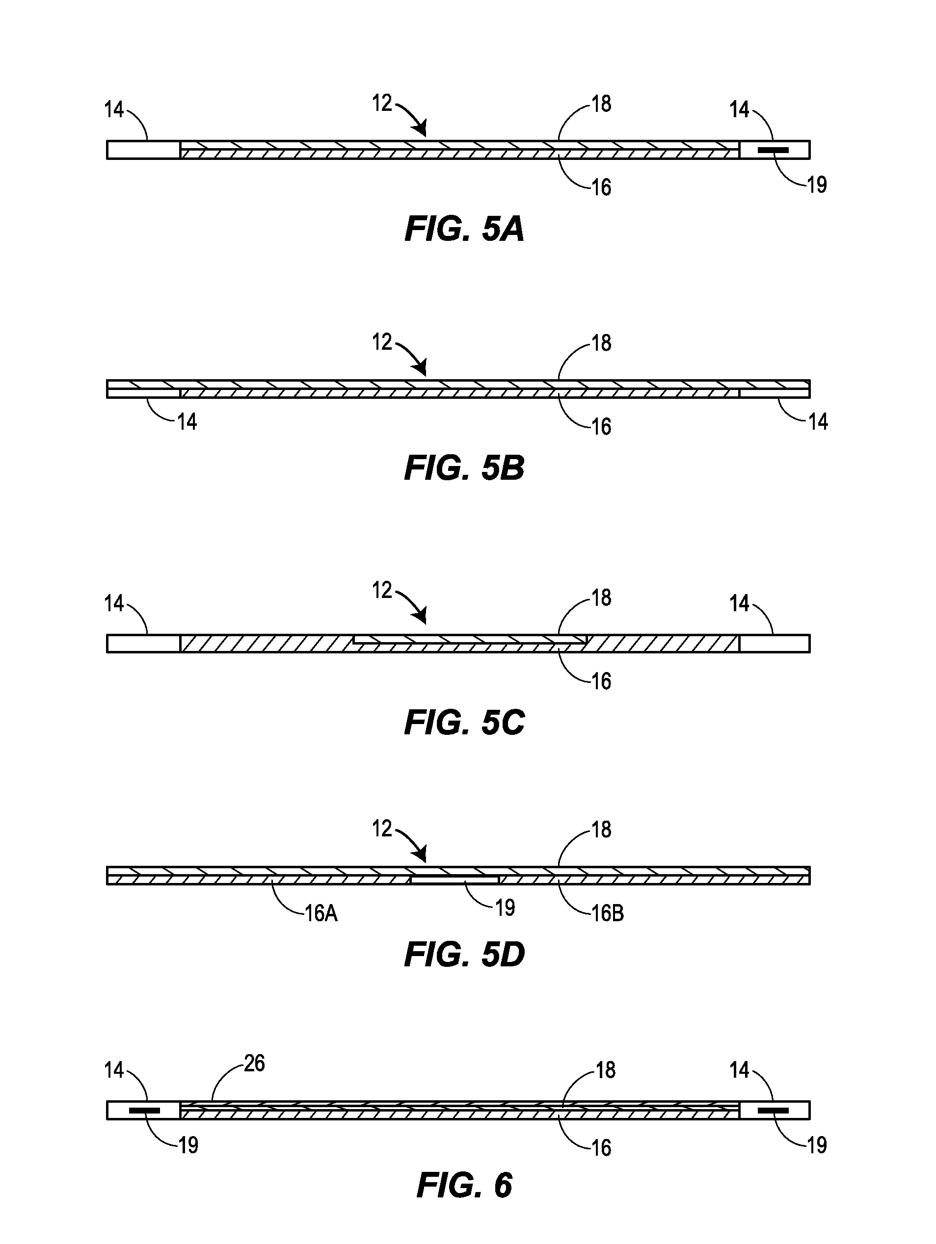
[0144]Referring now to FIG. 1, a dynamically flexible, attachable article 10, which is illustrated to be in the form of a wristband, includes a flexible band portion 12, which is generally rectangular in shape and configuration, disposed between two ends, which may include end pieces or fasteners 14. The band portion 12 includes a flexible support 16 and a flexible electronic display 18 disposed on the support 16 to be viewable from the top of the band 12, as illustrated in FIG. 1. One or more of the fasteners, end pieces, ends, or clasps 14, each of which may be made of hard plastic, metal, or other rigid material, but could instead be made of a pliable material, may include various electronic components therein for driving the flexible electronic display 18 and for providing other electronic functionality for the article 10. Additionally or alternatively, one or more various electronic components may be disposed in one or more electronic modules that are attached to the band 12 at...


PUM


Abstract

A dynamically flexible article or device, such as a wristband, an armband, a rollable e-reader, or a belt, includes a flexible electronic component (e.g., a flexible display) and a support structure coupled to the flexible electronic component. The support structure is configured to limit bending of the flexible electronic component to a range within a bending tolerance of the flexible electronic component.

Description

RELATED APPLICATIONS[0001]This application is a continuation of International Patent No. PCT / US14 / 72313 filed Dec. 24, 2014, which claims priority to and the benefit of the filing dates of U.S. Provisional Patent Application Ser. No. 61 / 920,705, entitled “Dynamically Flexible, Attachable Device Having an Integral Flexible Display” which was filed on Dec. 24, 2013 (Ref. No.: 32187-48118P); U.S. Provisional Patent Application Ser. No. 61 / 969,531, entitled “Dynamically Flexible, Attachable Device Having a Flexible Electronic Display” which was filed on Mar. 24, 2014 (Ref. No.: 32187-47794P2); U.S. Patent Provisional Application Ser. No. 61 / 979,668, entitled “Support Structure for a Flexible Electronic Component,” which was filed on Apr. 15, 2014 (Ref. No.: 32187-48292P); and U.S. Patent Provisional Application Ser. No. 62 / 003,549, entitled “Flexible Electronic Component Movably Coupled to a Flexible Support” which was filed on May 28, 2014 (Ref. No.: 32187-48467P). The entire disclosur...

Claims


Application Information

Patent Timeline
IPC IPC(8): G06F1/16
CPCG06F1/163G06F1/1652G09F9/301H05K1/0281G09F21/02H05K1/189H05K5/0017H05K5/0086H05K2201/051H05K1/183Y02E10/549A44C27/008A44C5/0015A44C5/0084H10K77/111
Inventor HUITEMA, HJALMAR EDZER AYCOINAGAKI, PHILIPPEMOK, KWOK WAHHAMERS, JOHANNES CORNELIS ADRIAAN
Owner FLEXTERRA INC
Why Eureka
Try Eureka