Ac-ac converter device

a converter device and converter technology, applied in the direction of ac-ac conversion, power conversion systems, electrical equipment, etc., can solve the problems of excessive switching losses and complex circuits

Active Publication Date: 2015-12-31
ELTEK
View PDF5 Cites 10 Cited by
  • Summary
  • Abstract
  • Description
  • Claims
  • Application Information

AI Technical Summary

Benefits of technology

[0024]In one aspect, the bidirectional switch includes a first BS switch and switch diodes (DBS1, DBS2, DBS3, DBS4). Here, a drain terminal of the first BS switch is connected to an anode of a first switch diode and to an anode of a second switch diode; a source terminal of the first BS switch is connected to a cathode of a third switch diode and to a cathode of a fourth switch diode; a cathode of the first switch diode and an anode of the third switch diode is connected to the first node; a cathode of the second switch diode and an anode of the fourth switch diode is connected to the second node; a control terminal of the first BS switch is connected to the control circuit.
[0025]In one aspect, the bidirectional switch includes a first BS switch and a second BS switch, each including control terminals connected to the control circuit.

Problems solved by technology

However there is a considerable drawback with this type of circuit since the center leg CL of the center half bridge Bc is common for the in / out rectifier stage (box Bin) and the output inverter stage (box Bout).
This circuit is rather complex, having 4 legs and 4 inductors.
A disadvantage of having a combination of two MOSFET switches in a half-bridge configuration switching with high frequency is the excessive switching losses coming from the recovery of the slow body-drain diodes.

Method used


Image

  • Ac-ac converter device
  • Ac-ac converter device
  • Ac-ac converter device

Examples


first embodiment

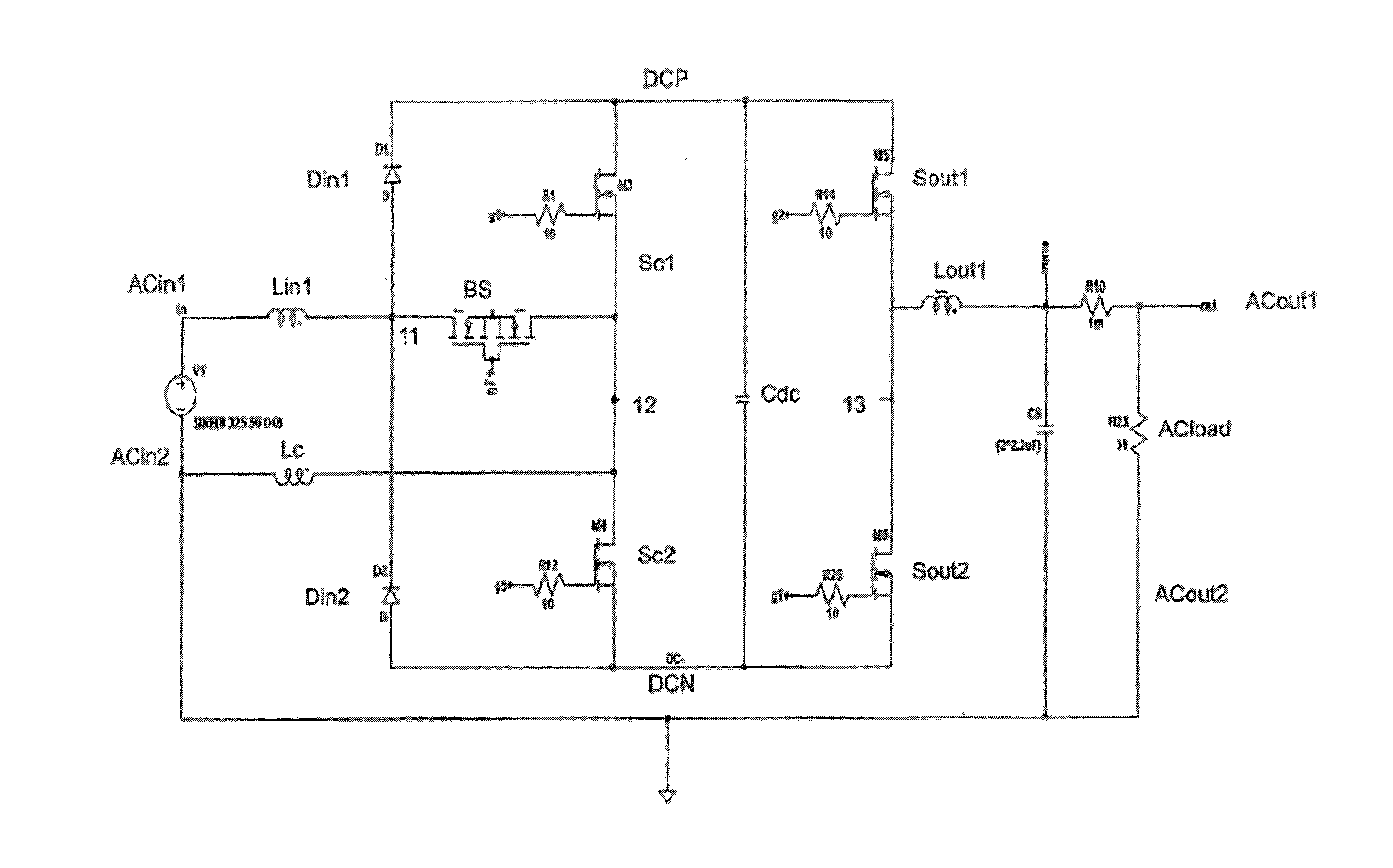
[0052]Alternatives of the bidirectional switch BS will now be described. In the first embodiment shown in FIG. 7 and in FIG. 8a, the bidirectional switch BS includes a first BS switch S1 and a second BS switch S2, each including control terminals GS1, GS2 connected to the control circuit. A drain terminal DS1 of the first BS switch S1 is connected to the first node 11, a drain terminal DS2 of the second BS switch S2 is connected to the third node 22, and a source terminal SS1 of the first BS switch S1 is connected to a source terminal SS2 of the second BS switch S2.

second embodiment

[0053]In a second embodiment shown in FIG. 8b, the bidirectional switch BS also includes a first BS switch S1 and a second BS switch S2. Here, a source terminal SS1 of the first BS switch S1 is connected to the first node 11, a source terminal SS2 of the second BS switch S2 is connected to the third node 22, and a drain terminal DS1 of the first BS switch S1 is connected to a drain terminal DS2 of the second BS switch S2.

third embodiment

[0054]In a third embodiment shown in FIG. 8c, the bidirectional switch BS includes a first BS switch Si and switch diodes DBS1, DBS2, DBS3, DBS4. Here, a drain terminal DS1 of the first BS switch S1 is connected to an anode of a first switch diode DBS1 and to an anode of a second switch diode DBS2. A source terminal SS1 of the first BS switch S1 is connected to a cathode of a third switch diode DBS3 and to a cathode of a fourth switch diode DBS4. A cathode of the first switch diode DBS1 and an anode of the third switch diode DBS3 is connected to the first node 11. A cathode of the second switch diode DBS2 and an anode of the fourth switch diode DBS4 is connected to the second node 22. A control terminal GS1 of the first BS switch S1 is connected to the control circuit.

[0055]In the description above, the common switches Sc1, Sc2 and the output switches Sout1, Sout2 are MOSFET switches or IGBT switches with an antiparallel diode. Preferably, the switches are silicon carbide MOSFETs or...


PUM


Abstract

An AC-AC converter device includes first and second AC input terminals and first and second AC output terminals. An input device is connected between an input node, a common node, a positive DC terminal and a negative DC terminal, wherein the input node is connected to the first AC input terminal via a first input inductor. An output device is connected between an output node, the positive DC terminal and the negative DC terminal, wherein the output node is connected to the first AC output terminal via an output inductor. A common device is connected between the common node, the positive DC terminal and the negative DC terminal, where the common node is connected to the second AC input terminal via a common inductor. A control device is provided for controlling the switches of the output device and the common device.

Description

CROSS-REFERENCE TO RELATED APPLICATIONS[0001]This application is a national stage application of PCT / EP2014 / 050129 filed Jan. 7, 2014, which claims priority to U.K. Application No. 1301189.5 filed on Jan. 23, 2013 and which claims priority to U.S. Provisional Application No. 61 / 755,791 filed on Jan. 23, 2013, the entire contents of which are hereby incorporated by reference.BACKGROUND[0002]One or more embodiments of the present invention relate to an AC-AC converter device.[0003]AC-DC-AC converters are used for line conditioning by converting an AC input power, for example the mains, to a controlled AC output power supplied to a load. The load is typically a load requiring a reliable AC voltage and a reliable frequency, such as IT equipment for critical mission applications. The DC voltage can be provided from a battery or any other type of energy storage. The DC voltage can also originate from a solar panel or a wind generator provided with a suitable energy conversion module. AC-i...

Claims


Application Information

Patent Timeline
Patent Type & Authority Applications(United States)
IPC IPC(8): H02M5/458
CPCH02M5/4585H02M7/217H02J9/062
Inventor BÄCKMAN, NILSROJAS, ROBERTO
Owner ELTEK
Why Eureka
Try Eureka