Calibration of Step Attenuator

a technology of attenuator and step, which is applied in the field of attenuator, can solve the problems of long time required to achieve accurate calibration, and achieve the effects of reducing the impact of mixer rl, increasing measurement uncertainty, and considerable averaging (and therefore time)

Active Publication Date: 2015-12-31
NATIONAL INSTRUMENTS
View PDF1 Cites 7 Cited by
  • Summary
  • Abstract
  • Description
  • Claims
  • Application Information

AI Technical Summary

Benefits of technology

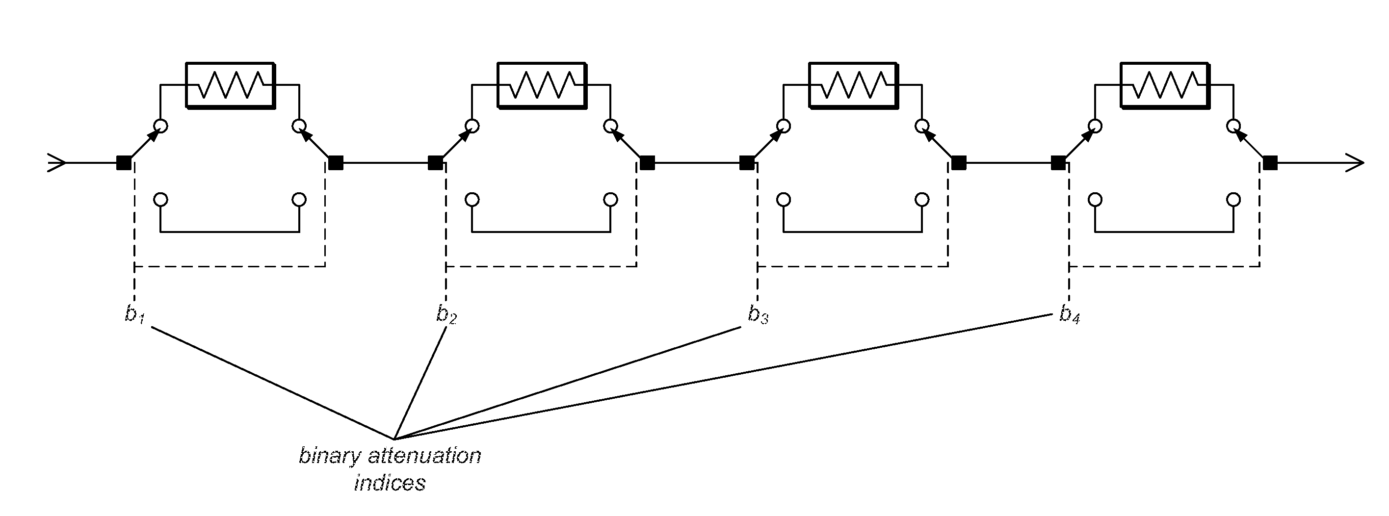
[0023]Note, however, that the value of the matrix “(matrix bT*matrix b)−1*(matrix bT)” is constant for a particular set of measured attenuation states. The coefficients at each new frequency may thus be determined by multiplying each new vector of measured data L, by the already calculated “(matrix bT*matrix b)−1*(matrix bT)”, providing for efficient computation. Additional computational optimization may be obtained for a given “(matrix bT*matrix b)−1*(matrix bT)” if so desired, e.g., by “unrolling” the matrix multiplication into its component values and omitting the products where the bij values are zero. This optimization may need to be customized for any particular set of measured states, but may provide for fastest execution by eliminating unnecessary multiplication and addition instructions.
[0027]Referring again to the exemplary case above, since the system of equations is over-determined with more than 5 measurements, some of the possible activation states may be omitted (e.g., from the measurements). This may be advantageous from at least two perspectives: first, for low attenuation values, especially at 0 dB, but also to some degree at 5 dB, there may be significant microwave mismatch (and therefore increased measurement uncertainty) resulting from mediocre input return loss (RL), e.g., of a first mixer interacting with the signal source used for calibration, and so omitting the low attenuation states may reduce the impact of the mixer RL; second, at very high attenuation, the signal level available, e.g., at a digitizer, is low, and so considerable averaging (and therefore time) may be needed to reduce noise and achieve acceptable accuracy. Accordingly, omitting measurements at the 0, 5, 65, 70, and 75 dB settings therefore may have the potential to both reduce test time, and at the same time increase the accuracy of the calibration, a rare example of doing less to get better results.

Problems solved by technology

This is a time consuming process, generally taking many hours to perform, and can suffer from inaccuracy at low attenuation settings due to mismatch uncertainty, and inaccuracy at high attenuation owing to poor signal-to-noise ratio (SNR) during calibration.
At high attenuation settings, the time required to achieve an accurate calibration can be quite long because increased averaging is required to compensate for poor SNR.

Method used


Image

  • Calibration of Step Attenuator
  • Calibration of Step Attenuator
  • Calibration of Step Attenuator

Examples


Embodiment Construction

Incorporation by Reference

[0044]The following references are hereby incorporated by reference in their entirety as though fully and completely set forth herein:

[0045]U.S. Pat. No. 4,914,568 titled “Graphical System for Modeling a Process and Associated Method,” issued on Apr. 3, 1990.

[0046]U.S. Pat. No. 5,481,741 titled “Method and Apparatus for Providing Attribute Nodes in a Graphical Data Flow Environment”.

[0047]U.S. Pat. No. 6,173,438 titled “Embedded Graphical Programming System” filed Aug. 18, 1997.

[0048]U.S. Pat. No. 6,219,628 titled “System and Method for Configuring an Instrument to Perform Measurement Functions Utilizing Conversion of Graphical Programs into Hardware Implementations,” filed Aug. 18, 1997.

[0049]U.S. Pat. No. 7,210,117 titled “System and Method for Programmatically Generating a Graphical Program in Response to Program Information,” filed Dec. 20, 2000.

TERMS

[0050]The following is a glossary of terms used in the present application:

[0051]Memory Medium—Any of va...


PUM


Abstract

System and method for calibrating a step attenuator. N attenuation measurements of a step attenuator may be received, where the step attenuator includes M series-connected attenuation sections. Each attenuation section may be configured to switchably provide a respective level of attenuation, where N is greater than M, and where the step attenuator may be modeled via M+1 coefficients, including a coefficient for a no-attenuation state and respective coefficients for the attenuation sections. Values of the coefficients may be determined via least squares estimation using the N attenuation measurements, thereby calibrating the step attenuator.

Description

FIELD OF THE INVENTION[0001]The present invention relates to the field of attenuators, and more particularly to a system and method for calibrating step attenuators.DESCRIPTION OF THE RELATED ART[0002]Step attenuators are devices or components that operate to switchably attenuate (decrease) signal amplitude in precise steps, i.e., that can apply multiple discrete levels of attenuation via switching.[0003]Traditional methods for calibration of step attenuators require characterization of the frequency response (loss versus frequency) through the attenuator for every attenuation step setting. This is a time consuming process, generally taking many hours to perform, and can suffer from inaccuracy at low attenuation settings due to mismatch uncertainty, and inaccuracy at high attenuation owing to poor signal-to-noise ratio (SNR) during calibration. At high attenuation settings, the time required to achieve an accurate calibration can be quite long because increased averaging is required...

Claims


Application Information

Patent Timeline
Patent Type & Authority Applications(United States)
IPC IPC(8): H03H7/24
CPCH03H7/24H01P1/22G01R35/00G01R27/28
Inventor KISER, JON R.
Owner NATIONAL INSTRUMENTS
Why Eureka
Try Eureka