Communications system

a communication system and radio access technology, applied in the field of radio access networks, can solve the problems of undesired interference to (or suffer undesired interference), undesired interference to (or suffer undesired interference) the transmission of these mobile devices, and the failure of corrective measures made by the base station to improve the interference perceived by the mobile device, etc., to achieve the effect of alleviating radio interference and reducing interference in the communications network

Active Publication Date: 2015-12-31
NEC CORP
View PDF4 Cites 19 Cited by
  • Summary
  • Abstract
  • Description
  • Claims
  • Application Information

AI Technical Summary

Benefits of technology

[0027]Embodiments of the present invention aim to provide improved techniques for alleviating interference in a communications network and, in particular, for alleviating radio interference caused to, or by, transmissions between a mobile communication device and nodes of a mobile (cellular) communication.

Problems solved by technology

The handing over of a mobile device might be necessary, for example, when the mobile device has moved away from the given base station, and also when an interference problem has arisen.
However, transmissions in the non-LTE frequency bands might, nevertheless, still cause undesired interference to (or suffer undesired interference resulting from) transmissions in the LTE bands, particularly in the overlapping or neighbouring frequency bands.
Such non-LTE radio technologies might be used by the mobile device itself or by other mobile devices in their vicinity and, although these radio technologies conform to the relevant standards (i.e. other than LTE), might still cause undesired interference to (or suffer interference from) the LTE transmission of these mobile devices.
Furthermore, since an LTE base station can control only the mobile device's (and its own) LTE transmissions, any corrective measures made by the base station would inevitably fail to improve the interference perceived by the mobile device because of the concurrently operated ISM transceiver.
In another typical scenario, the LTE transceiver of the mobile device can cause interference to the GNSS receiver (e.g. a GPS receiver) making it difficult to obtain a current location of the mobile device.
In this case, although there is no apparent disruption to the LTE signal (the signal quality measurements by the mobile device would indicate acceptable signal conditions), the LTE transmissions by the mobile device would be likely to render the GNSS functionality unusable because of the interference caused by the LTE transceiver to the GNSS receiver of the mobile device.
However, other bands and / or other radio technologies might also experience interference due to LTE / ISM / GNSS transmissions.
However, some IDC interference situations cannot be solved by the mobile device by itself, even if an ‘idc-config’ has been provided by the base station.
However, the above solutions are not always applicable for the so-called small cell enhancement scenarios defined in 3GPP TR 36.932 (v.12.1.0).
In such situations, interference may occur on either radio connection.
However, the mobile device is configured to receive its ‘idc-config’ settings (if any) from the macro base station, which settings are adapted to handle IDC situations arising in the macro cell (which carries the control plane only, in case of C / U-plane split) and thus cannot be used to tackle user plane interference experienced in the small cell.
Even if the ‘idc-config’ would be adapted and / or applied to small cells (or both macro cells and small cells), due to the relatively large number of small cells, and their possibly differing operating characteristics (compared to the macro cell and also to other small cells), such ‘idc-config’ would not be capable of addressing all the different possible IDC situations.
Furthermore, the mobile device can only send an IDC assistance indication to the macro base station (via which it has a control plane connection), not the low-power node handling its user plane connection.
However, given the relatively lower transmit power level used by the low-power node, user plane transmissions via the small cell might be more sensitive to interference than control plane transmission via the macro cell.
Even in the case when the mobile device experiences interference on the control plane and notifies this to the macro base station, any change in the macro base station's operation may cause unexpected interference for the user plane connection via the small cell.

Method used


Image

  • Communications system
  • Communications system
  • Communications system

Examples


Embodiment Construction

Overview

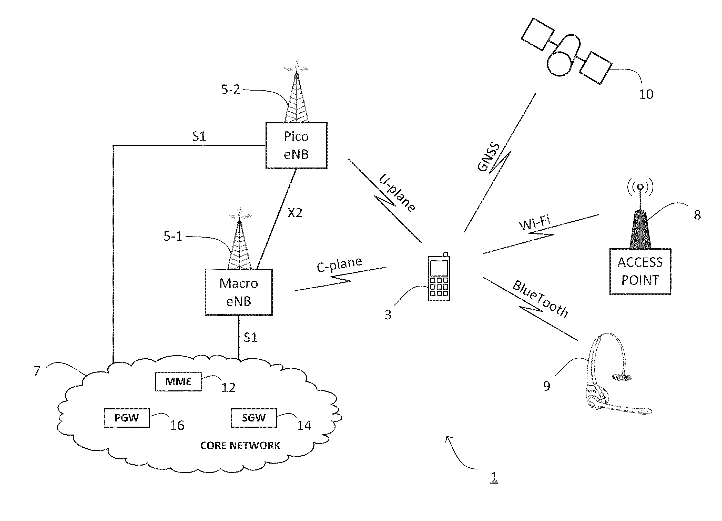
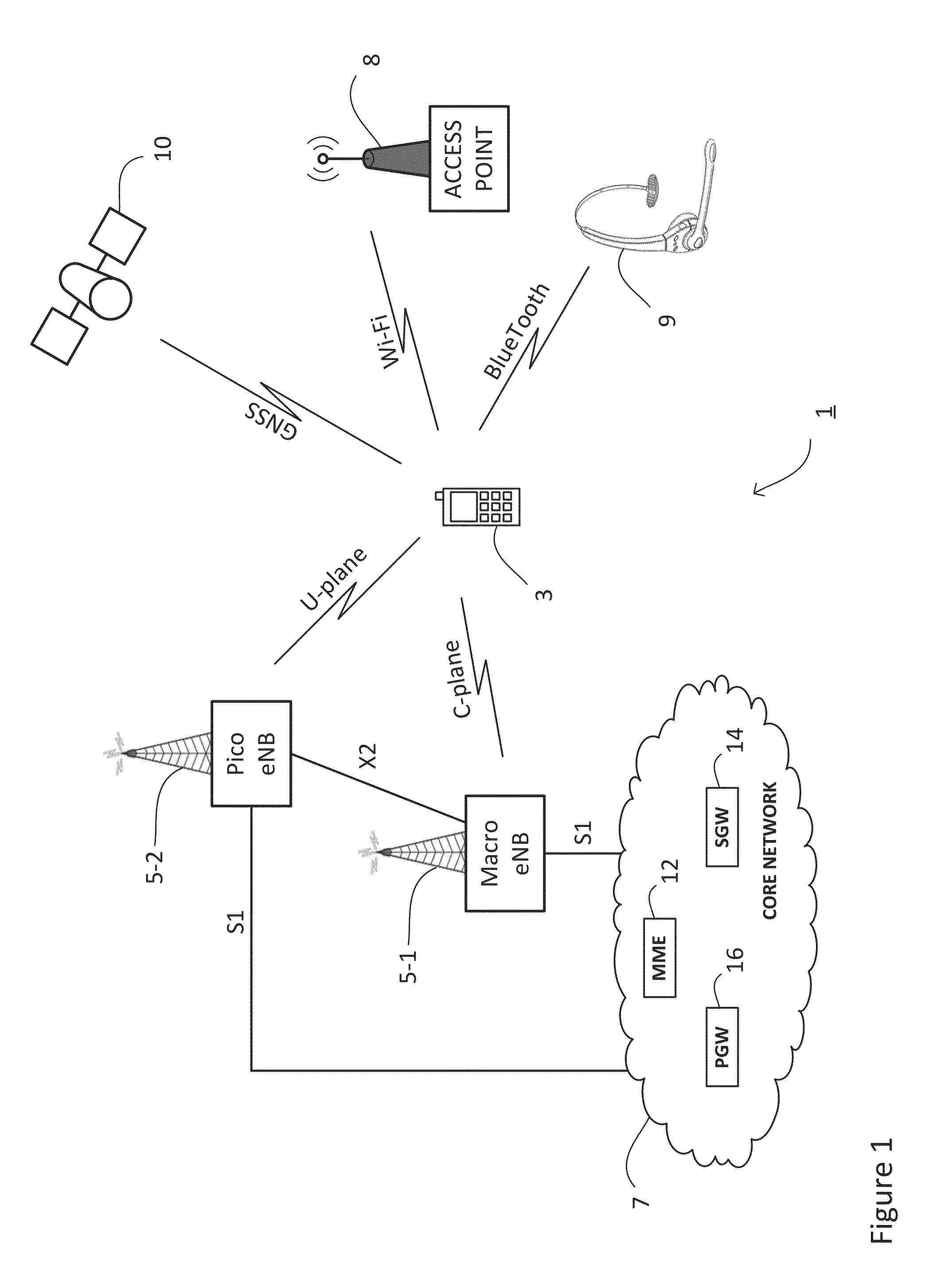
[0066]FIG. 1 schematically illustrates a mobile (cellular) telecommunication system 1 in which users of mobile devices 3 (for example mobile telephones) can communicate with other users via each of a plurality of base stations 5-1, 5-2 and a core network 7. In the system illustrated in FIG. 1, the base station 5-1 is a macro base station and the base station 5-2 is a pico base station (or other low-power node). Further base stations (not shown) might operate according to different standards, such as the Wideband Code Division Multiple Access (W-CDMA) or the GSM (Global System for Mobile Communications) EDGE (Enhanced Data rates for GSM Evolution) Radio Access Network (GERAN) standards or the like.

[0067]The core network 7 comprises a mobility management entity (MME) 12, a serving gateway (SGW) 14, and a PDN gateway (PGW) 16.

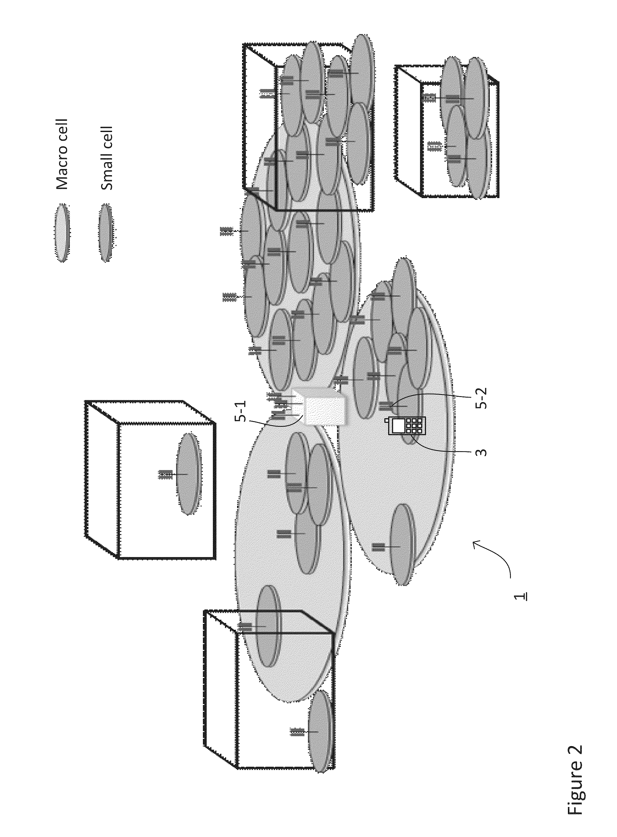
[0068]Each base station 5 operates at least one base station cell, each having a number of uplink and downlink communications resources (channels, sub-car...


PUM


Abstract

A mobile communications system is described in which a mobile device is operable to communicate with base stations using a first radio technology and with other devices using a second radio technology. The mobile device maintains a control plane connection with a first base station and a user plane connection via a second base station. In case of an interference is detected due to concurrent use of the first and second radio technologies, the mobile device provides assistance information to the base stations, based on which the base stations alleviate the effects of the detected interference.

Description

TECHNICAL FIELD[0001]The present invention relates to radio access networks in a cellular or wireless telecommunications network, and particularly but not exclusively to networks operating according to the 3GPP standards or equivalents or derivatives thereof. The invention has particular although not exclusive relevance to the Long Term Evolution (LTE) of UTRAN (called Evolved Universal Terrestrial Radio Access Network (E-UTRAN)) and to avoiding or reducing interference for mobile devices communicating with such networks; especially interference caused by, or to, non-LTE radio technologies used by the devices in addition to the LTE radio technology.BACKGROUND ART[0002]In a cellular communications network, mobile devices (also known as User Equipment (UE) or mobile terminals, such as mobile telephones) communicate with remote servers or with other mobile devices via base stations. An LTE base station is also known as an ‘enhanced NodeB’ (eNB). When a mobile device attaches to the LTE...

Claims


Application Information

Patent Timeline
Patent Type & Authority Applications(United States)
IPC IPC(8): H04W72/08H04W72/04
CPCH04W72/082H04W88/06H04W72/042H04W72/541H04W88/08H04W72/23
Inventor SHARMA, VIVEK
Owner NEC CORP
Why Eureka
Try Eureka