Printed shield with grounded matrix and pass through solder point systems and methods

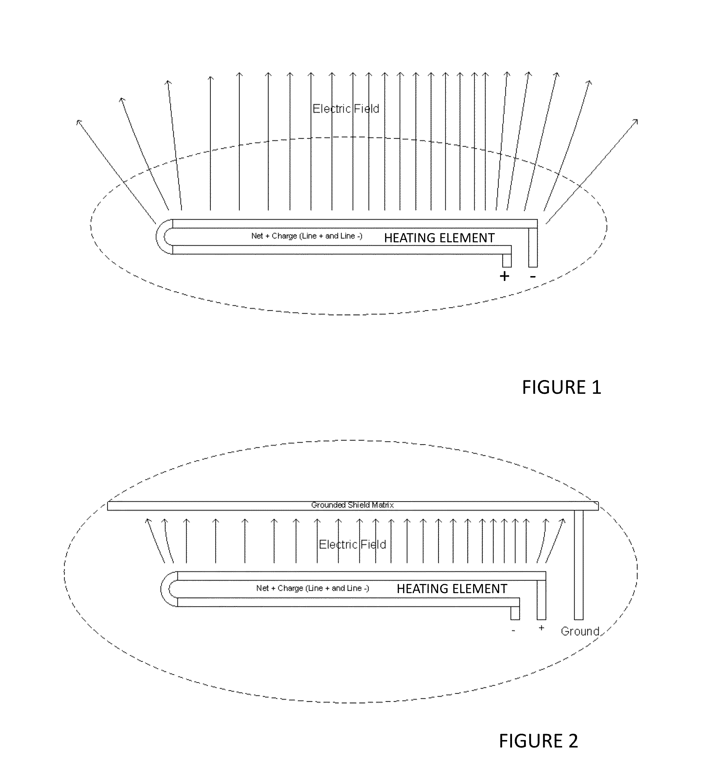
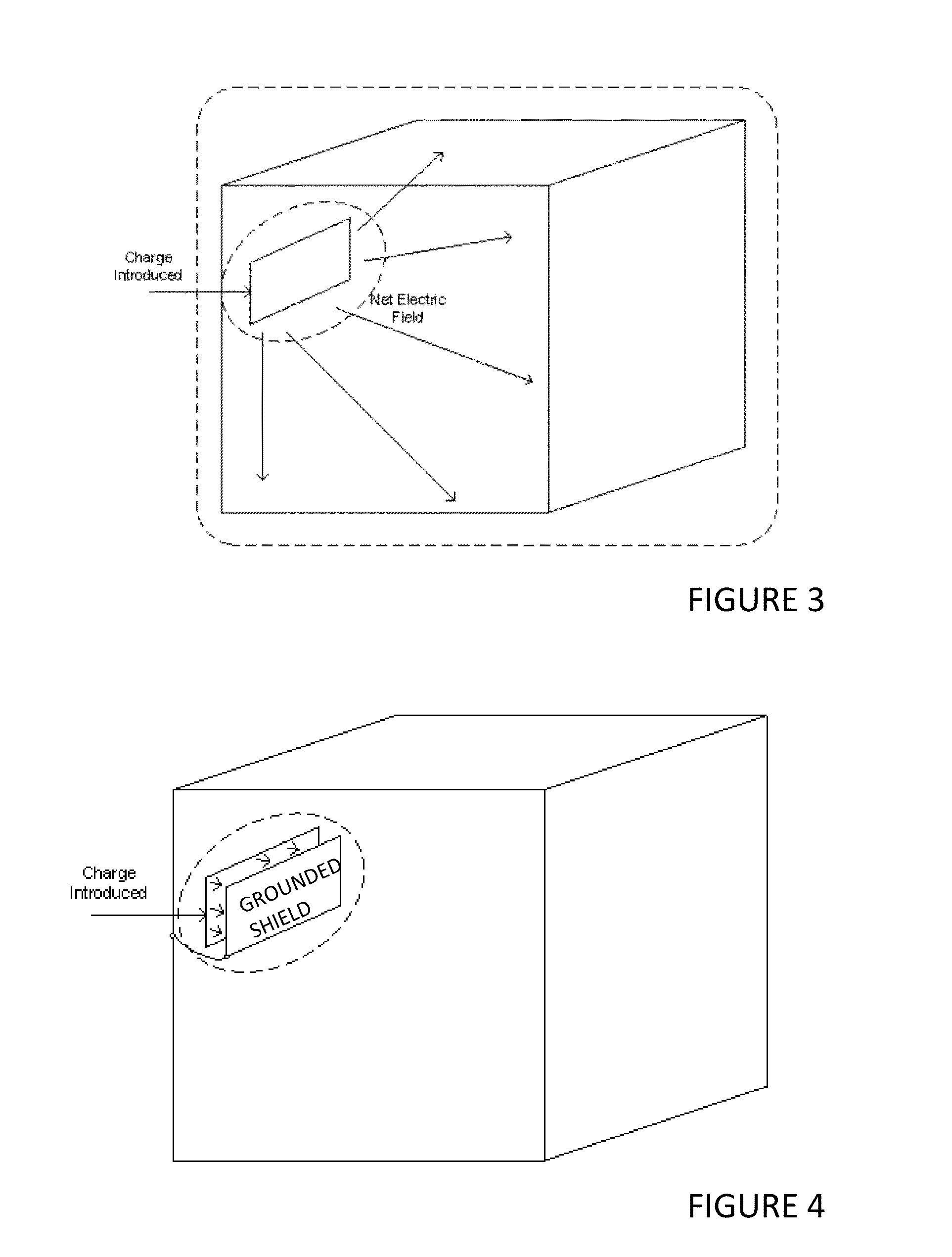
a technology of matrix and printed shield, applied in the field of infrared heating elements with ef shields, can solve problems such as inability to protect users from dangers, and achieve the effects of reducing or eliminating the emission of electric fields, reducing or eliminating electric fields

Active Publication Date: 2015-12-31
TYLOHELO
View PDF11 Cites 2 Cited by
  • Summary
  • Abstract
  • Description
  • Claims
  • Application Information

AI Technical Summary

Benefits of technology

[0010]Embodiments of the present invention relate to infrared (IR) systems for saunas, with such systems involving one or more infrared heating panels. Each panel is configured to include a substrate, and an IR heating element supported by the substrate. When energized, the heating element emits IR radiation. A return element is also supported by the substrate and generally forms a circuit with the IR heating element. One goal of the present invention is to reduce or eliminate the emission of electric fields into the sauna from the heating panels, in particular the IR heating element and at points of electrical coupling of the panels. Electric fields can be reduced or eliminated by a conductive shielding layer electrically coupled to earth ground and disposed between the source of the electric field and the area of desired field reduction. FIG. 1 illustrates an example of an IR heating panel generating an electric field in an unblocked configuration. Connected to the polar terminals of the heating element is a power source. The active heating element emits infrared heat and an electric field illustrated in the Figure as elongated arrows. An area defined by the dotted line is a zone inaccessible to users. As illustrated in the Figure, the electric field extends beyond the inaccessible area to other areas accessible to nearby users. This configuration is unable to protect the user from the dangers associated with exposure to the electric field.
[0014]Novel use of shielding of infrared panels is embodied here. Shielding may be printed directly onto the panel or substrate for position atop the IR heating elements so as to reside between the heating element and spaces that may be occupied by a user. The shielding may be connected to earth ground in order to prevent the buildup of electrical charge or the flow of induced electrical currents there through. Printing of a semi conductive shield having a resistivity greater than metals such copper or aluminum over a non-conductive substrate produces an EF shield of variable effectiveness. This disclosure also teaches methods to create a semi-conductive printed shield that exhibits a uniform and substantial EF shield along the entire surface of exposure.
[0021]Some embodiments that will be described herein generally provide power feeds, power feed connections, heating panels, saunas, and / or methods relating to design configurations that can in some cases reduce the electromagnetic field emissions emanating from the power connection to an electric heating panel.
[0025]Some embodiments may optionally provide none, some, or all of the following advantages, though other advantages not listed here may also be provided. In some cases, one or both of an extension conductor portion and / or return conductor portion of a power feed may be an integral portion of one of the insulated conductors providing power to the heating panel. In some cases, the return conductor is instead a separate insulated conductor physically connected to the end of the extension conductor. In some cases, the return conductor portion can be made by cutting off a portion of one of the insulated conductors of the power feed, twisting the portion about the extension conductor portion, electrically connecting the portion to the end of the extension conductor portion, and electrically connecting the opposite end of the portion to the second terminal.

Problems solved by technology

This configuration is unable to protect the user from the dangers associated with exposure to the electric field.

Method used


Image

  • Printed shield with grounded matrix and pass through solder point systems and methods
  • Printed shield with grounded matrix and pass through solder point systems and methods
  • Printed shield with grounded matrix and pass through solder point systems and methods

Examples


Embodiment Construction

[0056]The following detailed description is exemplary in nature and is not intended to limit the scope, applicability, or configuration of the invention in any way. Rather, the following description provides some practical illustrations for implementing exemplary embodiments of the present invention. Examples of constructions, materials, dimensions, and manufacturing processes are provided for selected elements, and all other elements employ that which is known to those of ordinary skill in the field of the invention. Those skilled in the art will recognize that many of the noted examples have a variety of suitable alternatives. Where applicable, like reference numbers will be used for like components, though like components need not be identical from embodiment to embodiment.

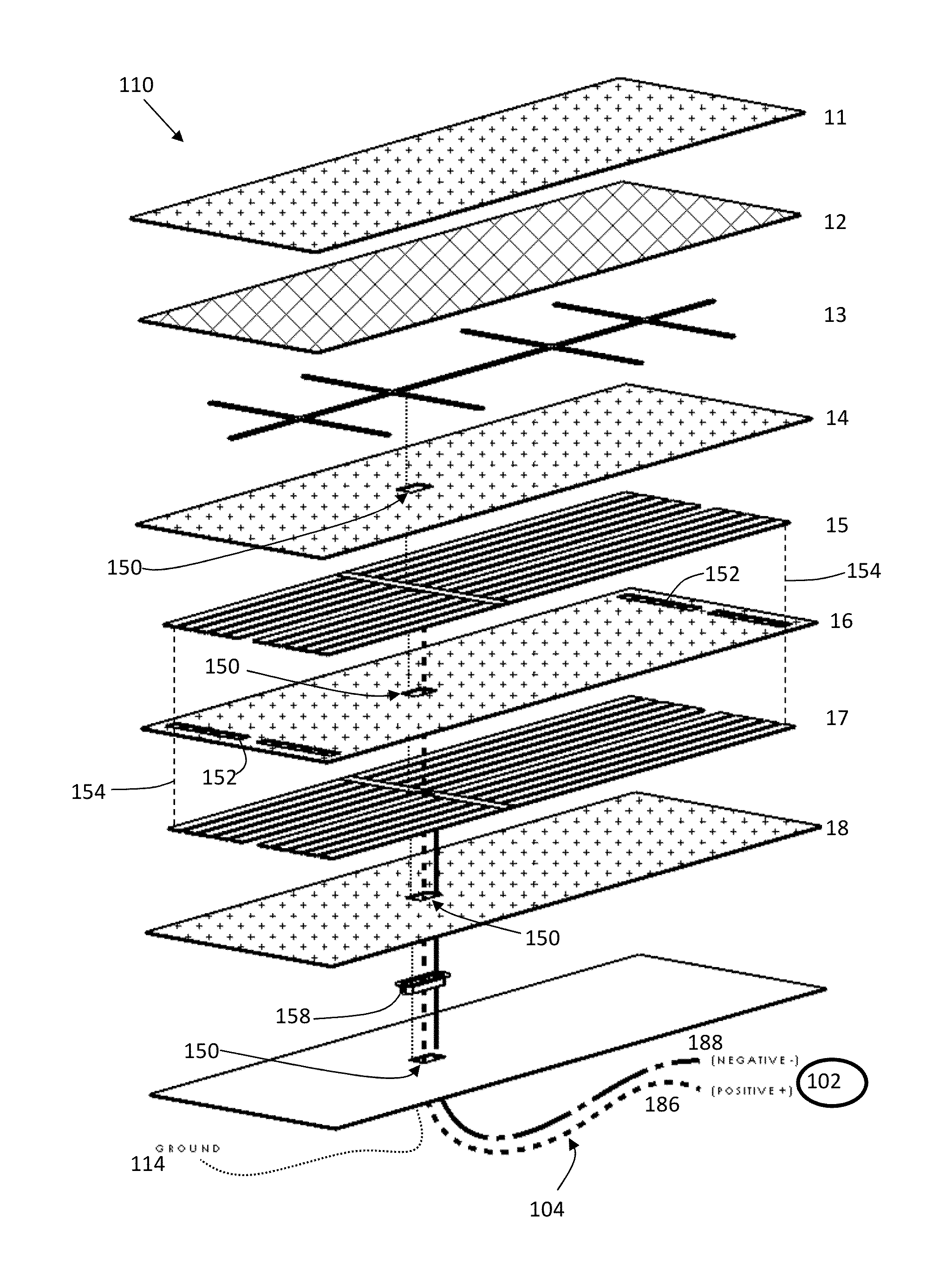
[0057]One example of a sauna is illustrated in FIG. 7. The sauna 100 includes a plurality of heaters illustrated here in the form of infrared heating panels 110. It should be appreciated that the sauna 100 depi...


PUM

PropertyMeasurementUnit
frequencyaaaaaaaaaa
frequencyaaaaaaaaaa
frequencyaaaaaaaaaa

Abstract

An infrared (IR) heating panel system comprising a thermally and electrically insulating substrate, a power buss, an at least one substrate supported IR heating element electrically coupled to the power buss, and a return element electrically coupled to the power buss and IR heating element. A printed shield substantially covers the IR heating element(s). The heating panel emits radiation when an electrical current is passed therethrough. The printed shielding layer is electrically coupled to a low impedance grounding matrix and configured to harness and shunt electrical field charges emitted by the IR heating element. Some embodiments include two or more IR heating panels coupled in an electrical parallel configuration supplied by one twisted and shielded power feed wire. Twisted two-wire shielded plus ground conductors are soldered to the corresponding IR heater solder points while simultaneously maintaining the twisted wire configuration for EMR cancellation and EF grounding shield conductivity.

Description

CROSS REFERENCE TO RELATED APPLICATIONS[0001]This application is also a continuation in part of application Ser. No. 13 / 837,087 filed Mar. 15, 2013 and application Ser. No. 13 / 665,040 filed Oct. 31, 2012 the entire contents of which are hereby expressly incorporated by reference herein.[0002]This application also claims the benefit of U.S. Provisional Patent Application No. 61 / 999,790 filed Aug. 5, 2014, and U.S. Provisional Patent Application No. 62 / 230,122 filed May 27, 2015, and U.S. Utility application Ser. No. 13 / 837,087 filed Mar. 15, 2013, and U.S. Utility application Ser. No. 13 / 665,040 filed Oct. 31, 2012, and CA Application No. 2,813,340 filed Apr. 18, 2013, and Europe Application No. 13169699.9 filed May 29, 2013, and CA Application No. 2794059 filed Oct. 31, 2012, and Europe Application No. EP12190904.8 filed Oct. 31, 2012, the entire disclosures of which are hereby incorporated by reference and relied upon.BACKGROUNDTechnical Field [0003]The invention relates generally ...

Claims


Application Information

Patent Timeline
Patent Type & Authority Applications(United States)
IPC IPC(8): H05B3/26A61H33/06H05B3/16F24D13/02H05B3/14H05B3/12
CPCF24C7/04H05B3/16F24D13/02A61H33/063Y02B30/26H05B3/20H05B2203/032Y10T29/49083A61H33/066Y02B30/00
Inventor BENDA, STEVEN JOHNBENDA, CHAD MATTHEWKAO, RAGIS H.C.
Owner TYLOHELO
Why Eureka
Try Eureka