Method for automatic classification separately collection and automatic transportation of the solid waste

a technology of automatic classification and solid waste, which is applied in the direction of waste collection and transfer, cocoa, sorting, etc., can solve the problems of high cost and time consumption of solid waste collection, huge challenge for dwellers, municipalities, businesses, etc., and achieves the effect of increasing the value of waste recycling, high efficiency, and extending the identifying rang

Inactive Publication Date: 2016-01-07
QIU ZEGUO
View PDF13 Cites 30 Cited by
  • Summary
  • Abstract
  • Description
  • Claims
  • Application Information

AI Technical Summary

Benefits of technology

[0026]Comparing the voluntary waste classification by citizens, Identifying and classifying the waste by the smart detector and sensor assembly and mechanic device is much accurate with very high efficient. It overcomes the limited indentifying ability of human and the faults caused by the human. It largely extends the identifying range of the waste, and makes the classification of the wastes much more detail that largely increases the value of the waste recycle. It saves the time, manpower, and reduces the liability of the citizen and user. It offers much more convenience to the citizen and user.
[0027]Comparing the fluidizing assembly, the invention, rolling fluidizing assembly (15) has the advantages of quiet, high efficient and power saving. It is equipped low rolling speed, and forms strong static, the designed sawtoothes and sharp cuts on the circumference of the saw and cut roller (201) substantively increases the efficient of the waste fluidizing. Because there is no noise, it will be widely used for the household waste collecting.
[0028]The invention, automatic pipeline transportation of the waste has the advantage of low cost, high efficient, low space occupying, and easy management. It substantively reduces the cost of the waste collection, power consumption, time consuming.
[0029]FIG. 1 is the section view of the method and it's apparatus. In it, the applicant in front is the automatic waste collector; the user going near the automatic waste collector, the lid (10) is automatically opened by infrared sensor assembly, putting the waste into the waste receptor (8), and following down to the waste selector (6), the optical detector (7) and the camera (11) get the form, moving, color, mark and character, ray absorptance and reflectance of waste, the piezoelectric sensor (33) gets the weight and density of the waste, the sonic, sounder, electronic and magnetic, thermoelectric and odor detector assembly (9) gets the temperature, collision sounder, structure, electric and magnetic, odor and elasticity of the waste, identifying the waste by the main board (21), putting the identified waste A in the selector (6) into the waste container (1) by the selector driving assembly (13) and rail (14), the identified waste B into the container (2), the identified waste C into the container (3), depositing the wastes in the containers; container (2) is mounted on the top of rolling fluidizing assembling (15), instructing by the supervisory control center (34), turning on the vacuume pump and turning the dispatcher valve toward to waste B recycle center (18), setting a pressure in the pipeline, the pressure sensor (22) set in the pipeline gets the difference of the pressure in the pipeline, and turns on the power of the automatic waste collector, driving by the motor (32), the different gear assembly (16) make the saw and cut roller (29) and the saw and cut roller (30) counter-rolling with different speed that forms the vertical saw and cut, and transverse cut and shred, which cut and saw the waste into particles, preventing the waste conglutination on the saw and cut rollers and directing the waste into the conducting tunnel by the comb (31), the sharp edge of the rolling screw push rod (28) and the fixed transverse cut (27) forms cut, the circumferential face of the rolling screw push rod (28) and the grooves (26) inside the tunnel goes further cut and grind the waste and push the waste going toward to the granularity controlling screen net (24) and cut (25), by setting the diameter of the hole on the granularity controlling screen net (24), cutting by the cut (25) and the granularity controlling screen net (24), getting the designed granularity of the fluidized waste particles, driving by the exporting pump (23) and the fluidized waste going through the automatic outlet valve (23) into the pipeline, and conducting waste B through the pipeline into the waste B recycle center (18) by the regional automatic dispatch valve (20); automatically cleaning the container and pipeline by the spray (12); modifying the working condition by a heater set in the conducting tunnel; the bottoms of container (1) and container (3) are sliding when container (1) and container (3) are moved toward the center by the container driving assembly (5), and push the identified wastes in the containers into the rolling fluidizing assembly (15); moving container (1) toward to center, push the waste A into the rolling fluidizing assembly (15), fluidizing waste A into fluidized waste particle, turning the regional automatic dispatch valve (20) toward to waste A recycle center (17), driving the fluidized waste A to waste A recycle center (17) by the regional pumper, moving container (3) toward to center, push the waste C into the rolling fluidizing assembly (15), fluidizing waste C into fluidized waste particle, turning the automatic dispatch valve (20) toward to waste C recycle center (19), driving the fluidized waste C to waste C recycle center (19) by the regional pumper; that getting the classified uniform waste A, waste B and Waste C without plastic package for valuable recycle; the controlling panel (4) set for managing the automatic waste collector; the statistic date recorded in the main board (21), including the monthly producing amount of each waste, producing time, working and troubleshooting reports are sent to the supervisory control center (34) by the instruction of the supervisory control center (34) through the remote information exchange system.
[0030]FIG. 2 is the section view of the rolling fluidizing assembly. Aim to reach at a quiet and high efficient fluidizing assembly; the invention designed the rolling fluidizing assembly. Driving by the different couple gear pair with low counter-rolling speed, the sawtooth and cut on the surface of the saw and cut roller forms a strong static, cut in the waste into particle without noise. In FIG. 2 the small gear (204) and large gear (205) make the saw and cut roller (201) and the saw and cut roller (202) counter-rolling with different speed that forms the vertical saw and cut, and transverse cut and shred, which cut and saw the waste into particles, preventing the waste conglutination on the saw and cut rollers and directing the waste into the conducting tunnel by the comb (203), the sharp edge of the rolling screw push rod (211) and the fixed transverse cut (213) forms the second transverse cutting, the circumferential face (212) of the rolling screw push rod and the grooves (214) inside the conducting tunnel goes further cut and grind the waste, and the face (215) of the rolling screw push rod pushes the waste going toward to the granularity controlling screen net (206) and cut (207), by setting the diameter of the hole on the granularity controlling screen net (206), cutting by the cut (207) and the granularity controlling screen net (206), getting the designed granularity of the fluidized waste particles; the heater (210) set in the conducting tunnel is the first to modifying the working condition to accommodate the winter; the second is to soft the waste, such as to make plastic soft, shrink and directly cut into grain, that gets renewed products, increase the efficient and optimize the waste recycle process; the third is to melt some waste, such as oil, and prevent it's conglutination.
[0031]FIG. 3 is the section view of the saw and cut roller couple. In it, the saw and cut roller are formed by the sawtooth (301) and cut (302), the comb (303) in between, when the large gear (306) and small gear (307) counter-rolling drives the saw and cut rollers rolling with difference speed, that forms the vertical saw and cut (305), and transverse cut, saw and shred (304), which cut, saw and shred the waste into particle and drive the waste particle following the comb (303) down to conducting tunnel and preventing the waste conglutination on the saw and cut rollers.

Problems solved by technology

Solid waste is a huge challenge for the dwellers, municipalities, industries, and businesses.
It is expensive and time consuming to collect millions of tonnes of trash every year, and there are risks to the environment.
In the modern time, the increasing consumption of commodity causes large contaminated plastic involved in the waste that devalues the waste.
It is time consuming, energy wasting, resource destroying, inconvenience and high cost.
Besides, it caused the wastes and the plastic package cross-contamination that devalues the wastes.
However, landfill and incinerating are pollutant transfer, which cause serious secondary pollution.
The urban expending causes the shortage of the landfill site.
The incinerating causes serious air pollution that threatens the health of the population and exacerbates the pollution of PM 2.5.
The municipalities face the big challenge of the solid waste.
Identifying and classifying the wastes by manual can cause faults easily, besides the waste collection and transportation depend the plastic package that cause much plastic and waste cross-contamination, increase the cost and difficulty for recycle and reuse.
The patents about food and closet waste disposers, which set under dishpan, galley sink as well as the spittoons, are limited on shredding food scraps and closet wastes to prevent the drainage jam.
It makes all of the waste scraps flush into public drainage system that causes the increase of waste water, consuming large of fresh water.
It transfers solid waste into wastewater that exacerbates the waste pollution, causes the difficult for purifying and largely increases the cost.
It cannot be widely practiced, because it is difficult to reach at the source of the waste, such as kitchen.
Besides it is easy caused the pipeline jam.
The cost for the pipeline construction, operation and maintenance are extremely high.
However, the classification of the waste has to depend the voluntary identification by human and the fluidizing assembly has to equip with high speed motor that could cause the noise and reduce the efficient.
The identifying ability of human and citizen is limited.
It is difficult for the human and citizens to identify.

Method used


Image

  • Method for automatic classification separately collection and automatic transportation of the solid waste
  • Method for automatic classification separately collection and automatic transportation of the solid waste
  • Method for automatic classification separately collection and automatic transportation of the solid waste

Examples


Embodiment Construction

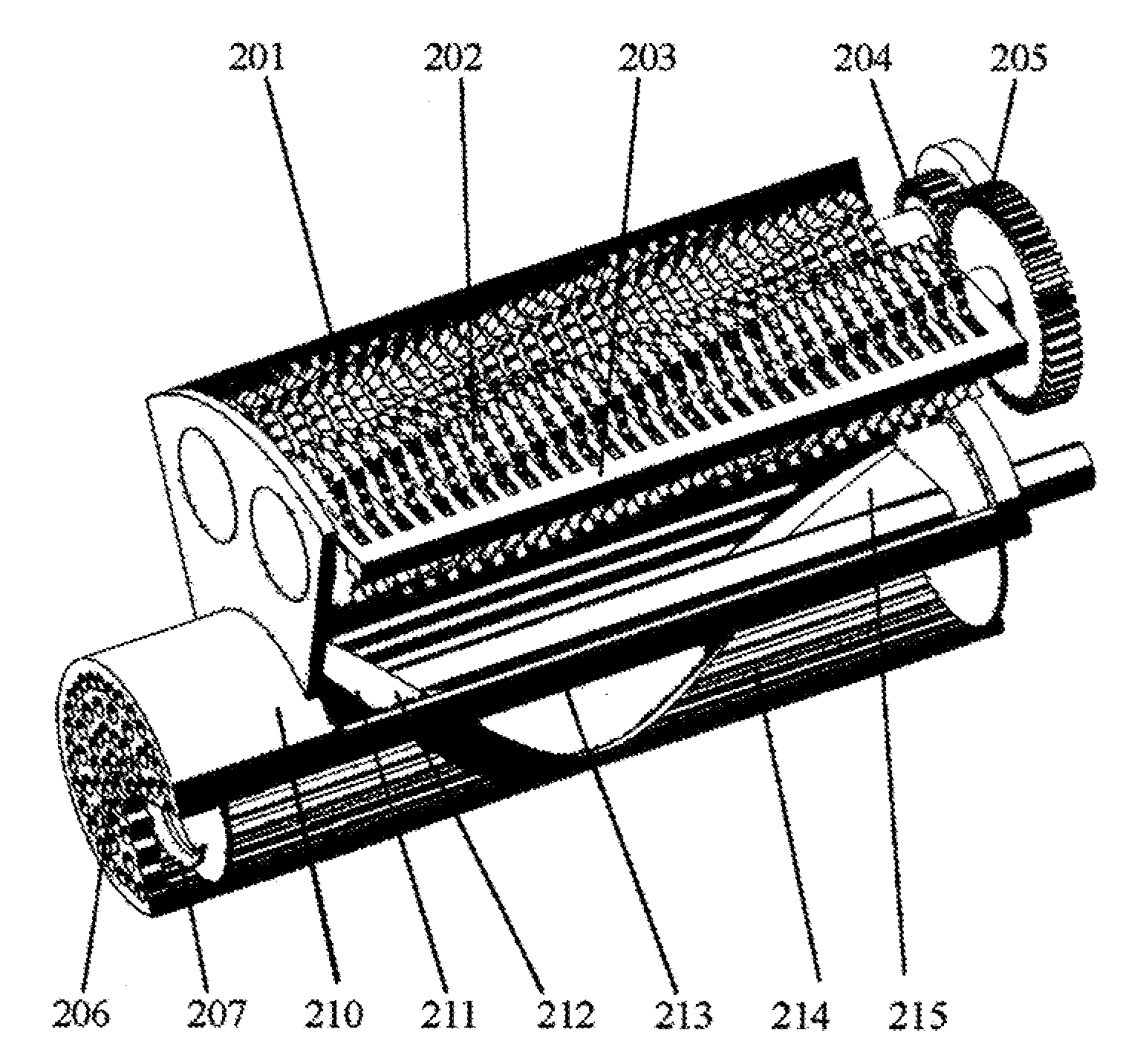
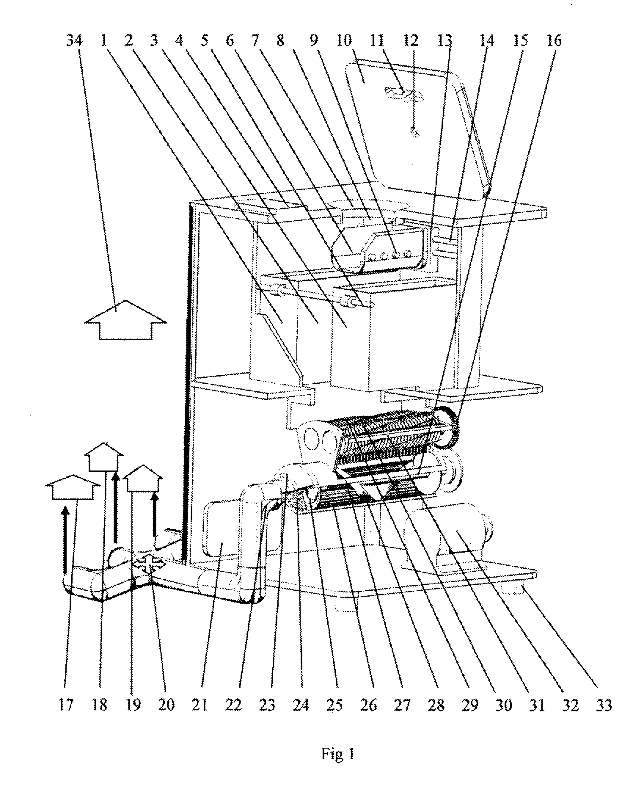
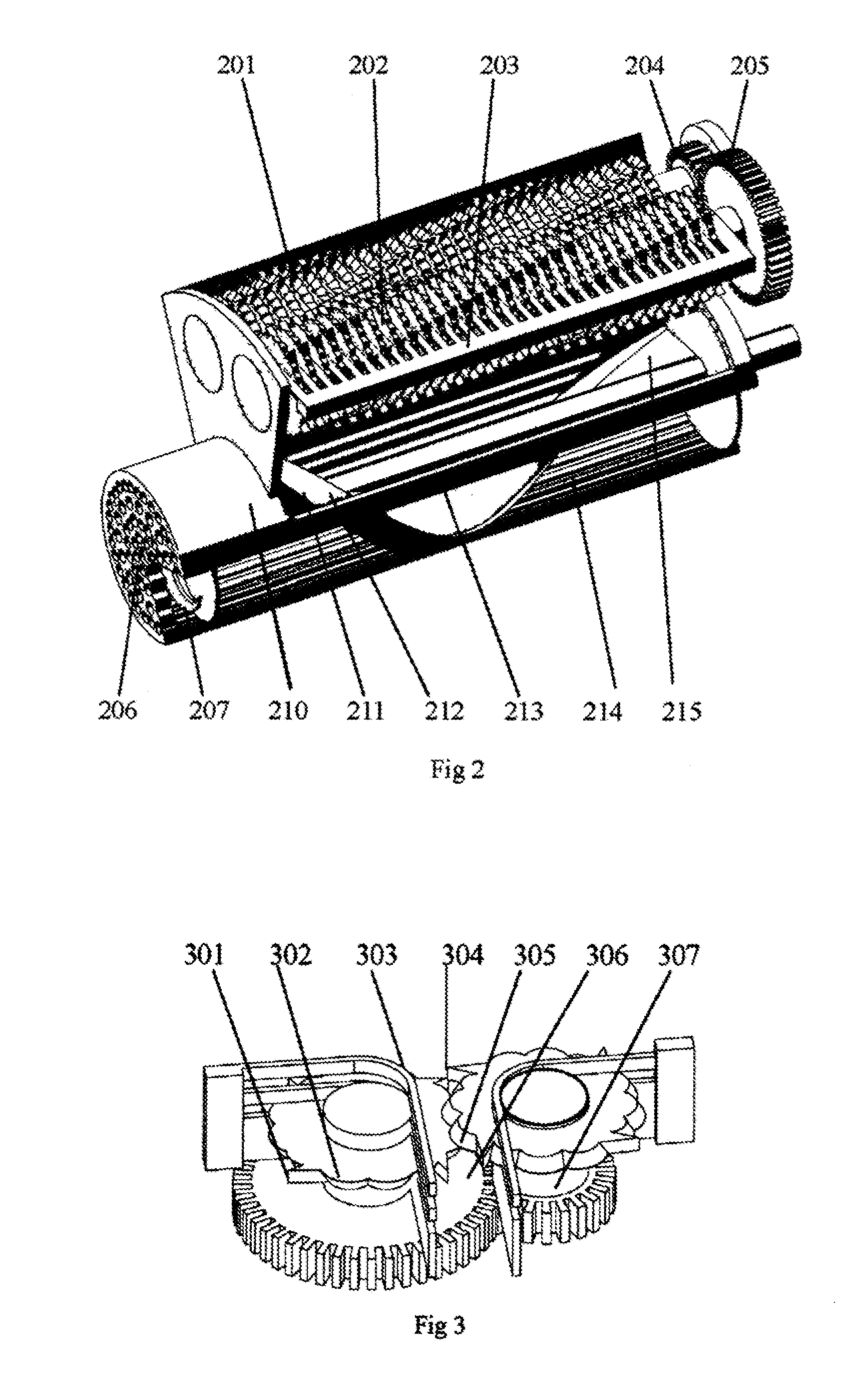
[0021]With reference to accompanying drawings, the present invention, the method automatic classification is explained in details. the component of the waste is very complex, however each waste has it's distinct of appearance, color, form, physical, chemical. Besides, there are many marks and characters on the waste from the consumed commodity, such as bar code, dimensional code. To reach at simplifying and high efficient, the invention designed the identifying and classifying method of:

1. Reading identification, defining the color, mark, character, code, bar code and dimensional code of each waste, and getting the data from commodity, inputting the data of the color, mark, character, code, bar code and two dimensional code of each waste into the main board, putting the waste into the receptor (8), scanning and reading the color, mark, character, code, bar code and two dimensional code on the waste by the optical detector (7) and camera (11), identifying the waste by the main board ...


PUM


Abstract

A method for automatic classification separately collection and automatic transportation of the solid waste is designed to replace the manual door to door collection of the waste by the computer, and getting the waste for valuable recycle and reuse comprises of putting the waste into the automatic waste collectors set at the source of the waste producing and connected with pipeline, identifying the waste by the main board (21), classifying the waste by the selector (6), depositing the waste in the containers (1), (2) and (3), fluidizing the wastes by rolling fluidizing assembly (15), under the monitoring of the supervisory control center, separately transporting the wastes into the correspond waste recycle center, and getting the solid waste automation.

Description

[0001]This application claims the benefit under 35 USC 119 to application 201310331283.3 filed in China on Jul. 27, 2013 and to application 201310547452.7 filed in China on Nov. 7, 2013.BACKGROUND[0002]1. Field of the Invention[0003]The present invention, a method for automatic classification separately collection and automatic transportation of the solid waste, pertains, in general, to the solid waste automation, which the municipal waste can be separately collected by the management of computer, to the automatically classifying, automatic separately collection and transportation of the solid waste, to all kinds of the solid wastes automatically classifying, automatically collecting, automatically discharging, automatically transporting, and getting the renewable uniform and simplified wastes for recycling and reuse.[0004]2. Background Art[0005]The municipal waste will be separately collected by the management of computer in the head office. An method for automatic classification s...

Claims


Application Information

Patent Timeline
Patent Type & Authority Applications(United States)
IPC IPC(8): B02C23/08B02C18/00B02C25/00B07C5/34
CPCB02C18/0092B02C23/08B02C25/00B07C5/34B02C18/0084B02C18/142B65F5/005B65F1/0033B65F2210/126B65F2210/128B65F2210/138B65F2210/152B65F2210/168B65F2210/184B65F2210/20Y02W30/10B02C23/06B02C23/14
Inventor QIU, ZEGUO
Owner QIU ZEGUO
Why Eureka
Try Eureka