Inlet closure system

a closure system and inlet technology, applied in the direction of tank wagons, sliding roofs, wagons/vans, etc., can solve the problems of affecting the access to the inlet, the sheet must be stored when, and the piston rods project above the end walls of the wagon body, so as to improve the structural strength of the wagon body

Active Publication Date: 2016-01-07
DRAX POWER
View PDF8 Cites 12 Cited by
  • Summary
  • Abstract
  • Description
  • Claims
  • Application Information

AI Technical Summary

Benefits of technology

[0030]The substantially upright support member, which may be included to improve the structural strength of the wagon body, may advantageously provide the common pivot for the ends of the first links

Problems solved by technology

However, this type of cover system must be operated manually, and has the further disadvantage that the sheet must be stored when it is not in use.
One disadvantage of this design is that when the doors are fully open, such as during the loading of the wagon, the piston rods project above the end walls of the wagon body.
As a result, the piston rod

Method used


Image

  • Inlet closure system
  • Inlet closure system
  • Inlet closure system

Examples


Embodiment Construction

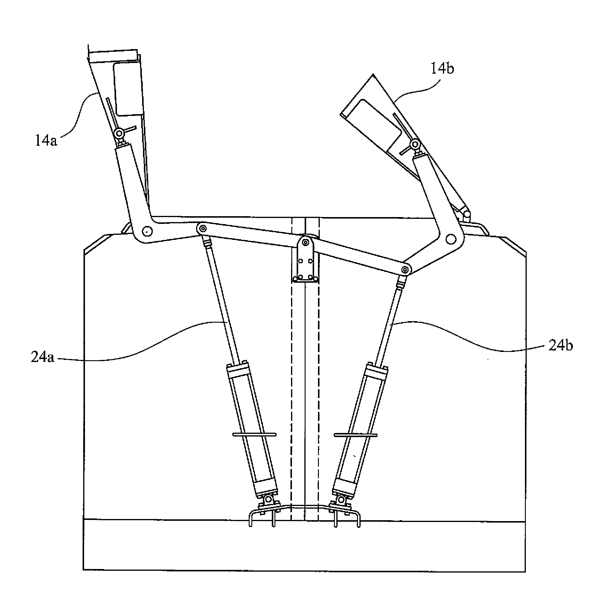
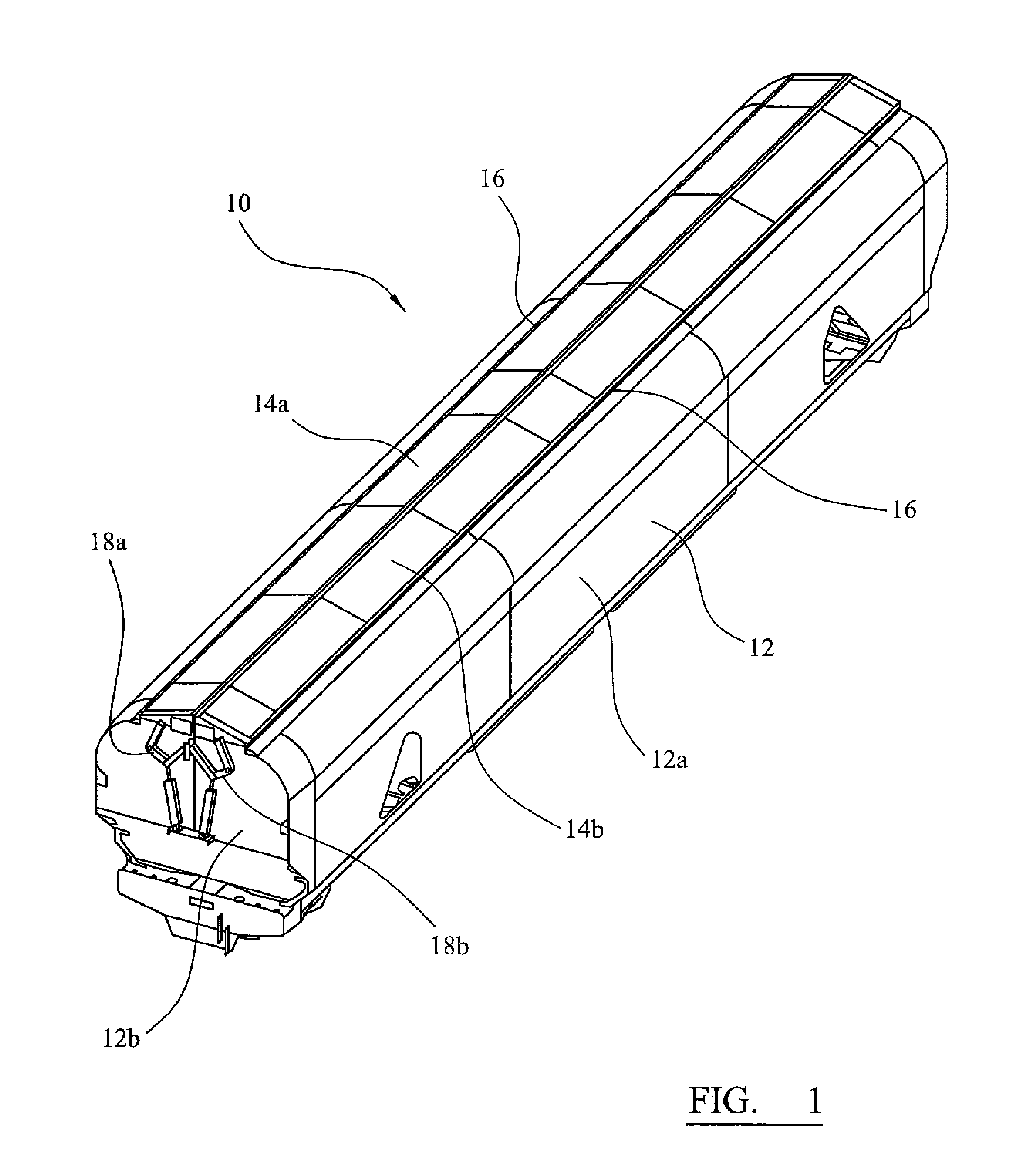
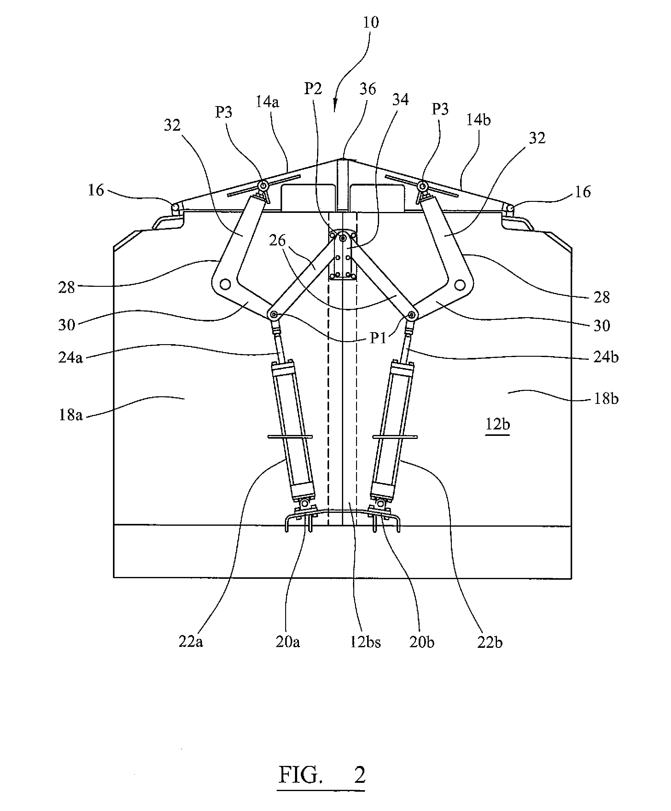
[0043]The invention relates to an inlet closure system for covering an inlet formed in an upper region of a container body. The container body may be a storage region of a storage device such as a hopper, hopper vehicle or inter-modal container box.

[0044]FIGS. 1 and 2 show a closed hopper rail wagon (10) for use in transporting bulk freight. The wagon comprises an elongate wagon body (12) of steel, comprising sidewalls (12a) and end walls (12b), defining an enclosure within (not shown in FIGS. 1 and 2) for containing a bulk commodity. The wagon comprises an inlet (I) formed in the top of the body. The inlet has a generally rectangular shape and it is defined by upper edges of the sidewalls and the end walls. The wagon further comprises outlets formed in the bottom of the body (not shown). The body (12) is supported on an under-frame (not shown). Beneath the under-frame is a pair of bogies (not shown), for engagement with a railway track in use. The bogies have been omitted from thes...


PUM


Abstract

The invention relates to an inlet closure system for covering an inlet formed in an upper region of a container body The container body may a storage region of a hopper, a hopper vehicle such as a hopper railway wagon or other storage devices. The inlet closure system comprises at least one closure member arranged substantially above the inlet and moveable between a first closed configuration in which the inlet is substantially closed and a second fully open configuration in which the inlet is substantially open, and at least one actuator mounted on an end wall of the container body for moving the closure member. The actuator remains below an upper edge of the end wall when the closure member is in the second fully open configuration. The actuator is arranged in use to act upon the at least one closure member via a linkage, which linkage is arranged for pivotal motion relative to the end wall about a point substantially midway between the side walls. The linkage may comprise a first link and a second link. The second link may have a first and a second limb which meet at a non-straight angle. Preferably, the first limb and/or the second link lie below the upper edge of the end wall when the closure member is in the second fully open configuration. The second limb may lie substantially beyond an inward facing surface of the closure member when the closure member is in the second fully open configuration. If two actuators are arranged to act upon respective closure members, the first links of the linkages are arranged to pivot about a common pivot point. The common pivot point is preferably located on the end wall at a point substantially midway between the sidewalls.

Description

FIELD OF INVENTION[0001]The present invention relates to an inlet closure system for a storage container and is concerned particularly, although not exclusively, with an inlet closure system for a covered hopper wagon.BACKGROUND TO THE INVENTION[0002]A hopper wagon is a type of freight railway vehicle for transporting bulk commodities. Typically the bulk commodity is held in a generally box-shaped hopper wagon body that is supported by an under-frame. The underframe may be coupled to bogies so that the hopper wagon can be moved along a railway track.[0003]The bulk commodity may be loaded into the hopper wagon body through an inlet aperture at the top of the wagon body, and may be discharged through an outlet aperture at the bottom of the wagon body. In covered hopper wagons, the inlet is provided with a cover to protect the bulk commodity held in the hopper wagon body.[0004]The cover may comprise a simple removable sheet. However, this type of cover system must be operated manually,...

Claims


Application Information

Patent Timeline
IPC IPC(8): B61D39/00B61D3/00
CPCB61D39/001B61D39/006B61D3/00B61D5/08B61D7/00B61D39/002
Inventor GIBNEY, RICHARD PETERJONES, STEPHEN JOHNBARLOW, JONATHAN JAMES
Owner DRAX POWER
Why Eureka
Try Eureka