Spring loaded actuator assembly

Active Publication Date: 2016-01-07
ITT MFG ENTERPRISES LLC
View PDF3 Cites 16 Cited by
  • Summary
  • Abstract
  • Description
  • Claims
  • Application Information

AI Technical Summary

Benefits of technology

[0029]a coil spring having ends attached to the rod and the second tubular member wherein translational movement of the second tubular member beyond a predetermined axial position causes the ramp-like teeth of the second tubular member to extend beyon

Problems solved by technology

The problem for the foregoing is in providing a spring actuat

Method used


Image

  • Spring loaded actuator assembly
  • Spring loaded actuator assembly
  • Spring loaded actuator assembly

Examples


Embodiment Construction

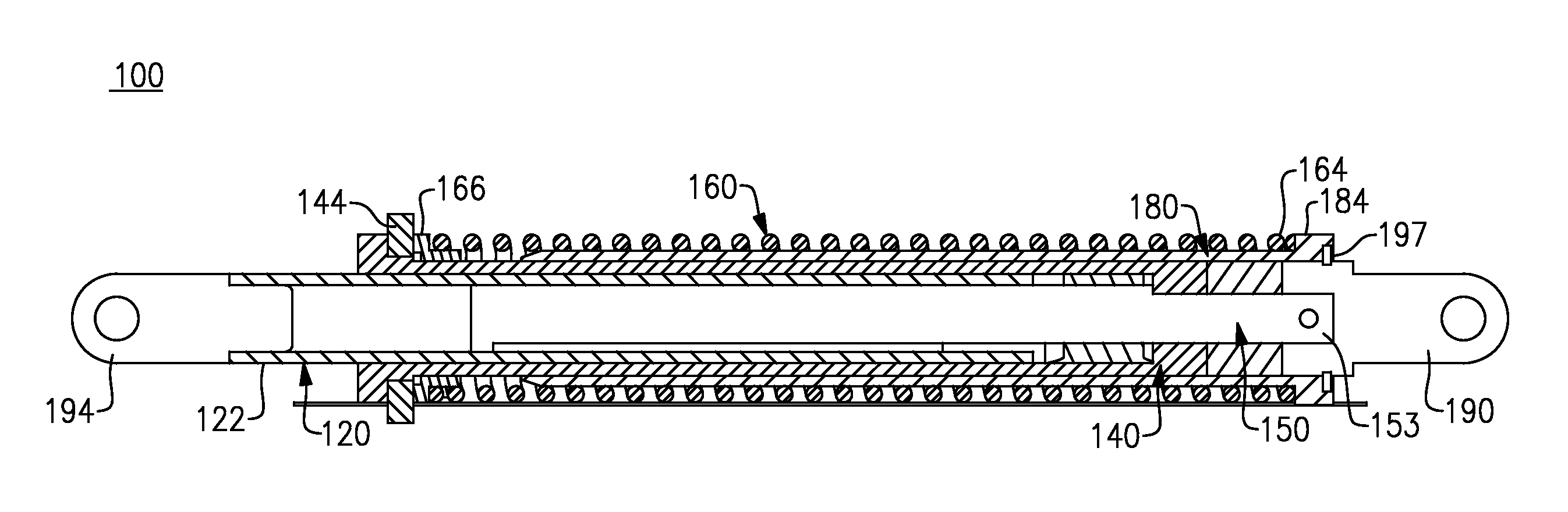
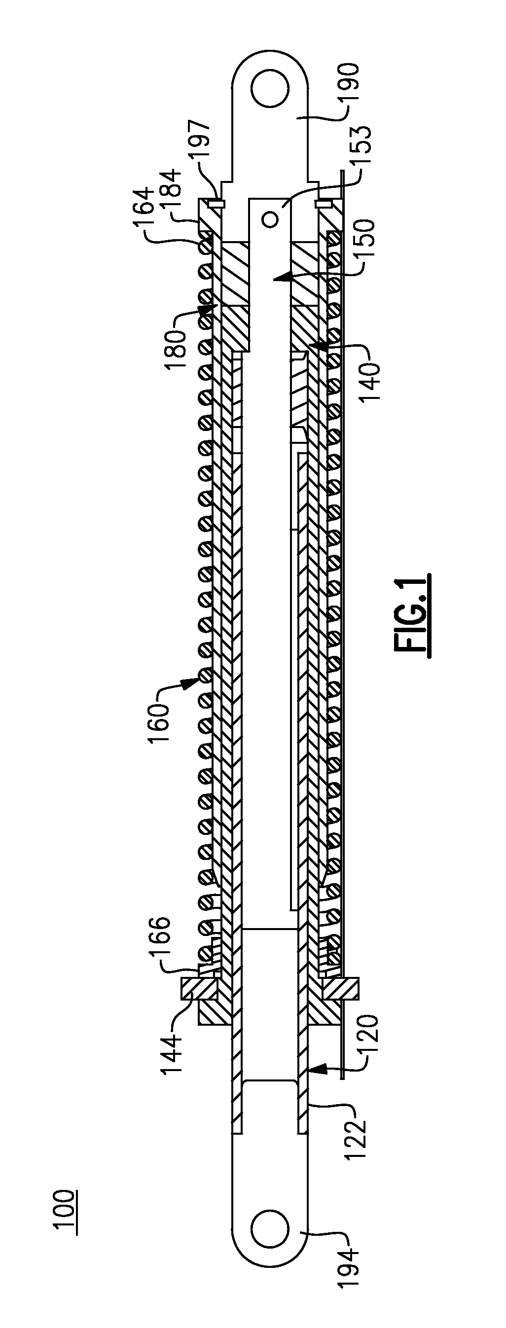
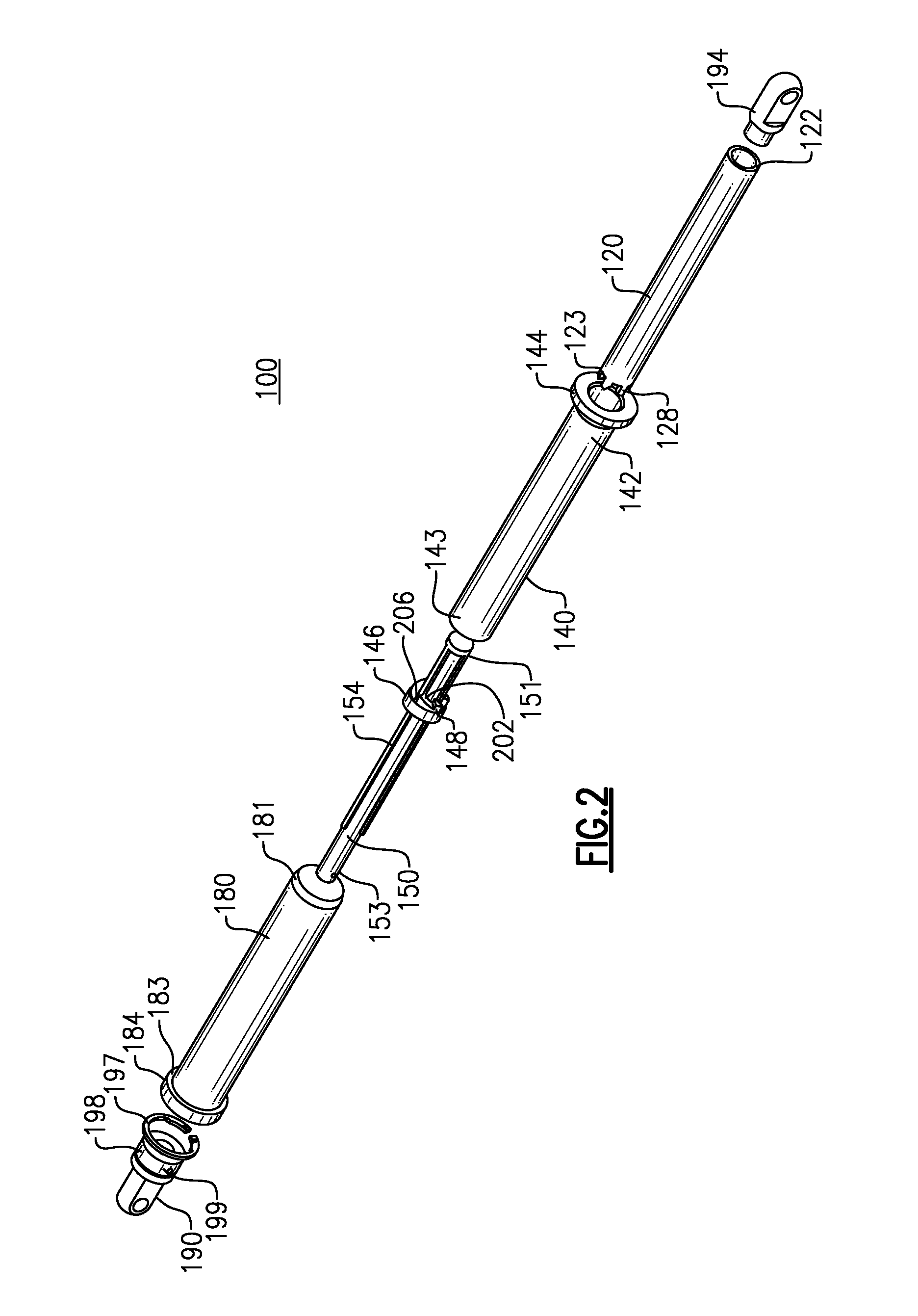
[0045]The following relates to various exemplary embodiments of a spring loaded actuator assembly for use in specific applications. However, it will be readily apparent that the actuator assembly can assume other configurations and that other suitable applications can be employed using the inventive concepts discussed herein.

[0046]Certain terms are used throughout the course of this description in order to provide an adequate frame of reference in regard to the accompanying drawings. These terms which may include “upper”, “lower”, “distal”, “proximal”, “inner”, “outer”, “above”, “below”, “within”, “interior”, “exterior” and the like should not be so interpreted to preclude the scope of the inventive concepts described herein, including the appended claims, unless so specifically indicated.

[0047]In addition, the accompanying drawings are merely intended to adequately and specifically convey the inventive concepts of the herein described spring actuator assembly and typical use enviro...


PUM


Abstract

A spring loaded actuator assembly includes a first member having a set of rails, a second member configured to translate axially relative to the first member and a third member configured for translational movement within the second tubular member. The second and third members each include a set of ramp-like teeth configured to engage one another when the third member is moved within the second member; and grooves configured to engage the rails of the first member and permit translational movement of the second and third members relative to the first member while preventing rotational movement of the second and third members. A coil spring is disposed between the first and second members wherein translational movement of the second member beyond a predetermined axial position causes the ramp-like teeth of the second member to extend beyond the rails, causing the second member to rotate and the ramp-like teeth to be retained by the rails of the first member, thereby maintaining the coil spring in a compressed condition while enabling the third member to be freely movable axially.

Description

TECHNICAL FIELD[0001]This application is directed to a spring-loaded actuator assembly that enables an assist force to be selectively retained and released relative to an object, such as an aircraft stowage bin, in order to reduce the amount of force required to open and close the object, for example, depending on the amount of weight that is present or in the presence of an over center condition.BACKGROUND[0002]There are a number of assemblies that utilize actuators, such as those presently found in and used in the opening and closing of an object, such as a door or enclosure mechanisms. According to one example, requirements dictate that the hand force required to close a pivot type stowage bin on a commercial aircraft can be no more than 25 lbs when the stowage bin is loaded with luggage. As a result, there is a general need in the field to provide a device that can provide a sufficient lift assist force when needed, therefore decreasing the hand force that is required to close t...

Claims


Application Information

Patent Timeline
IPC IPC(8): E05F1/14E05F1/10
CPCE05F1/14E05Y2900/54E05F1/105B64D11/003
Inventor JANAK, JOHN M.BOERSCHIG, TIMOTHY J.OTT, MARK J.
Owner ITT MFG ENTERPRISES LLC
Why Eureka
Try Eureka