Eureka AIR delivers breakthrough ideas for toughest innovation challenges, trusted by R&D personnel around the world.

Hydrogen-powered energy-producing device and system for continous production of hydrogen

a technology of energy-producing devices and hydrogen, which is applied in the direction of indirect heat exchangers, electrochemical generators, lighting and heating apparatus, etc., can solve the problems of inability to meet the needs of continuous use, so as to achieve the effect of increasing the rate of production and overall yield of hydrogen, increasing the rate of hydrogen production, and increasing the yield

Inactive Publication Date: 2002-07-11
UT BATTELLE LLC
View PDF0 Cites 16 Cited by
  • Summary
  • Abstract
  • Description
  • Claims
  • Application Information

AI Technical Summary

Benefits of technology

[0010] It is a further object of the present invention to provide a hydrogen generating system, which is easy and relatively inexpensive to regenerate.
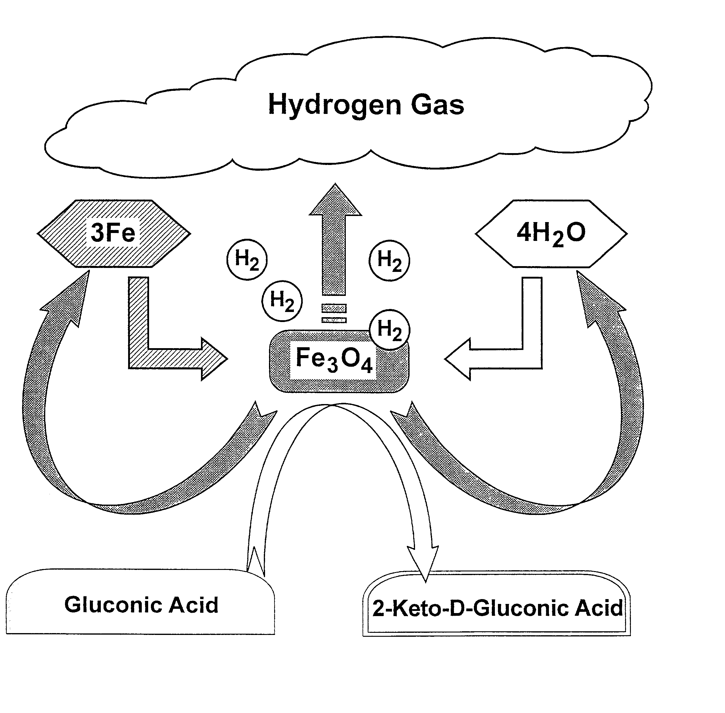
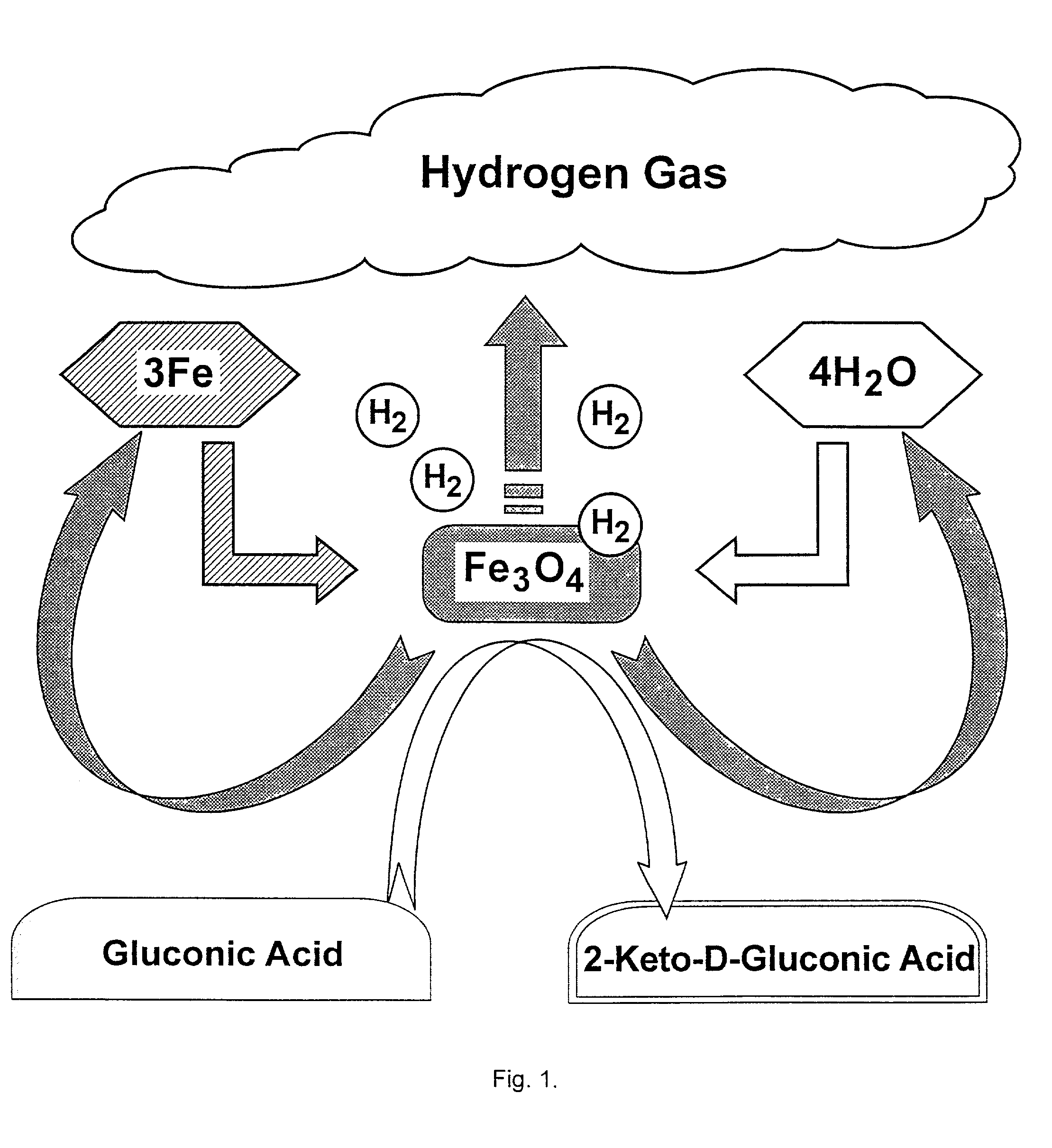
[0060] Iron oxidation is the mechanism for the generation of molecular hydrogen gas from the water component of the organic acid solution. The oxygen of the water binds to the iron and subsequently releases the hydrogen molecules. Hydrogen evolution is reduced when free molecular oxygen reacts with iron forming the iron oxide. Therefore, in order to minimize this effect, the solution is placed under vacuum and free oxygen and other gasses are removed prior to the solutions addition to the reaction vessel. The overall assists in maintaining anaerobic conditions. Degassed organic acid solutions have more than double the rates of hydrogen production when compared to the production rates with non-degassed solutions (FIG. 5). In the reaction containing 25 mg of iron powder, the non-degassed Hepes organic acid solution resulted in a peak production rate of 0.5 .mu.mol / hr, where as the degassed solution produced hydrogen at a peak rate of 4.4 .mu.mol / hr.
[0094] The metal catalyst can also be fixed to a surface within the reaction vessel, then the acid solution is forced over the catalyst at various rates. Also, the catalyst can be applied as a solid, such as a wire or mesh type system. These are examples of ways to reduce the amount of metal catalyst suspended in solution during the stirring process.
[0100] Micro-power sources can be used for low power (current) requiring electronic devices that could be placed in the environment for at least 1 year for sensing operations. They would also be portable and extremely light to carry and could generate power upon demand. Applications include audio / video equipment, cameras, communications, electronics, musical instruments and cellular phones. In view of escalating oil prices and potential shortages as well as the environmental consequences of hydrocarbon combustion, a macro-power system built on the methodology of Applicant's invention could prepare the military for a long-term sustainable energy supply around which could be built aircraft as well as other military vehicles. The benefits could also include the deployment of energy efficient cost effective power systems for providing light in work areas and living quarters. Military and non-military waste iron for hydrogen generation could also be utilized.

Problems solved by technology

While hydrogen is a clean and renewable energy resource, it is both expensive to produce in a pure form and unsafe to store in quantity due to its combustibility.
Moreover, hydrogen is expensive and heavy when stored in containers of practical size.
However, because the metal is consumed during the reaction, this process is cost prohibitive.
Also, the conversion rate of the reaction is extremely low unless the water or aqueous solution has been heated to very high temperatures which results in a low overall efficiency and thus it has no current practical commercial utility.
Therefore, it is not a practical method of hydrogen production from an industrial point of view.
Water or steam is thermodynamically incapable of decomposing into hydrogen and oxygen within the stated temperatures.

Method used


Image

  • Hydrogen-powered energy-producing device and system for continous production of hydrogen
  • Hydrogen-powered energy-producing device and system for continous production of hydrogen
  • Hydrogen-powered energy-producing device and system for continous production of hydrogen

Examples


example 2

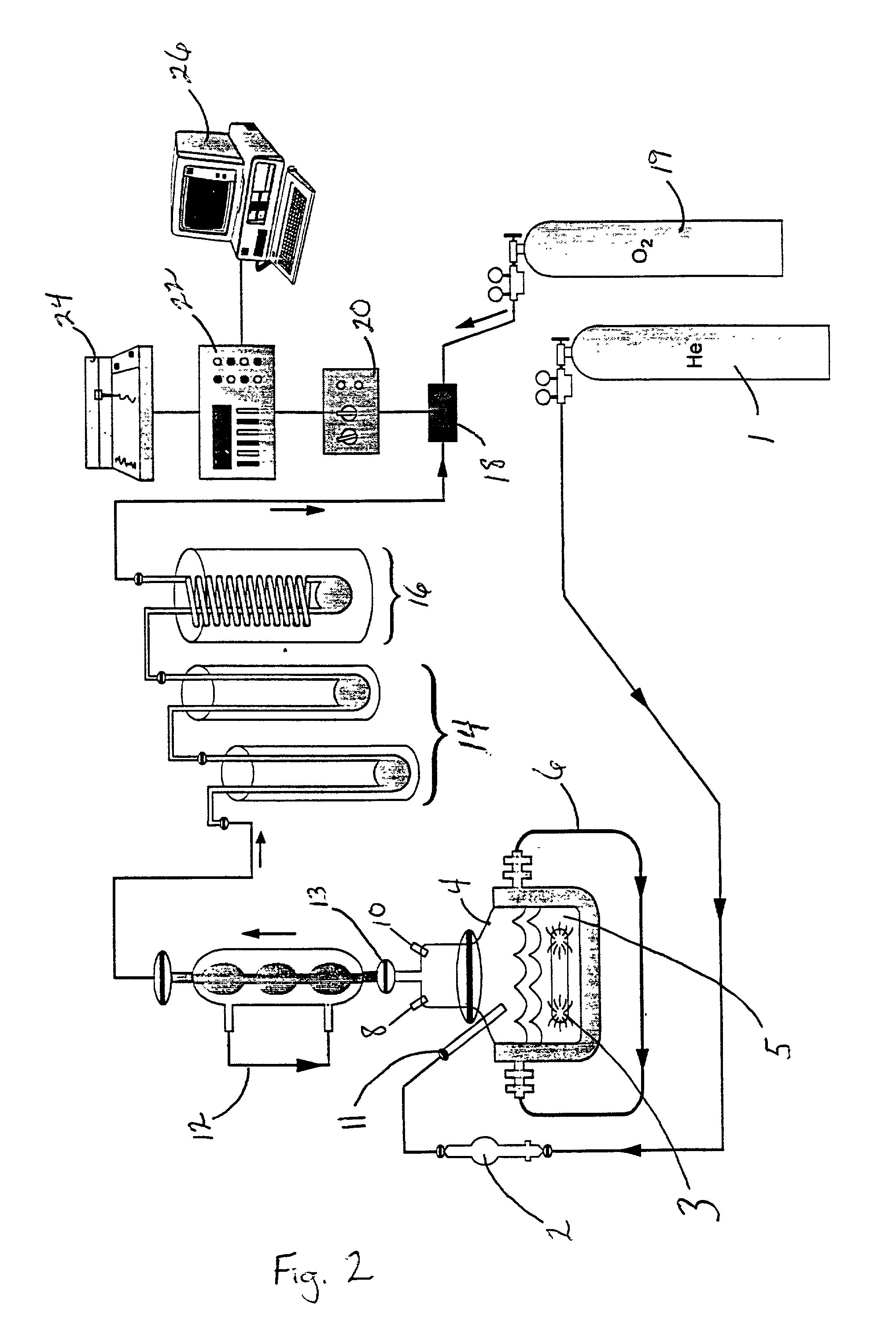
[0098] A housing device 89 was designed and assembled specifically for the fuel cell 94, see FIG. 14a (front view). The hydrogen gas flowed into the housing device 89 first passing through a glass frit 86. The housing device 89 comprised a first glass disc 92 and a second glass disc 92' with a fuel cell 94 sandwiched in between the two glass discs 92 and 92'. Rubber seals 96 were placed between the glass discs 92, 92' and the fuel cell 94. The housing device 89 was held together by lock-down bolts 90 and 90'. The housing device 89 had a gas inlet for atmospheric oxygen 98 and a gas outlet for the excess hydrogen gas 100 that can be used to be recycled back to the reaction step in the reaction vessel. The housing device 89 was connected to a digital clock by wire 102. FIG. 14b shows a top view of the fuel cell 94, 5 mm in diameter. From FIG. 15, it can be seen that the hydrogen fuel cell 94 was connected to the reaction system after the liquid nitrogen gas trap 16, in place of the hy...

example 3

[0104] A system having a solid / liquid volume of 5.0 ml comprises 0.1 g iron (Fe) powder (1.8 mmol) in 5% acetic acid. Based on Faraday's Law, generation of 5 .mu.amps of current requires the production of 15.5.times.10.sup.-10 mol / min H.sub.2. Since 1.8 mmol Fe generates an equimolar amount of hydrogen, then equipment with a current drain of 5 .mu.amps or 5 .mu.amps could run for 806 or 0.806 days respectively. The rate of H.sub.2 generation would need to be 0.093 or 93 .mu.mol / h. Maximum power generation =0.116 watt-h, depending on the efficiency of the fuel cell. This is based on the consumption of 1 mol H.sub.2by a fuel cell generating 237.1 kJ of free energy for a power requiring process.

example 4

[0105] A system having a solid / liquid volume of 5.0 ml comprises 1.0 g Fe powder (18 mmol) in 43% acetic acid. Based upon Faraday's Law, generation of 1200 mA of current requires the production of 372 .mu.mol / min H.sub.2. Since 18 mmol Fe generates an equimolar amount of hydrogen, then equipment with a current drain of 1200 mamps (e.g. cellular phone) could run for 48 minutes. Maximum power generation =1.16 watt-h.

[0106] Macro-power Generating System


PUM

PropertyMeasurementUnit
temperaturesaaaaaaaaaa
pHaaaaaaaaaa
flow rateaaaaaaaaaa

Abstract

The present invention is an energy-producing device powered by a system for the continuous production of hydrogen comprising a reaction chamber containing reactant components under anaerobic conditions whereby hydrogen is continually produced when the reactant components react with one another. The device further comprises a fuel cell adjacent the reaction chamber wherein the hydrogen produced is to be used as fuel and is diffused into the fuel cell; the fuel cell has positive and negative electrodes to convert the hydrogen into energy. The present invention also includes a hydrogen-generating system for the continuous and sustained production of hydrogen.

Description

CROSS-RELATED APPLICATIONS[0001] The present application is a continuation-in-part application to U.S. application Ser. No. 09 / 675,870 filed Sep. 29, 2000, incorporated herein by reference.[0003] The present invention relates to an energy-producing device having a continuous source of fuel in which to operate, particularly a hydrogen-powered energy-producing device fueled by a system for the continuous production of hydrogen based on a hydrogen-producing reaction cycle wherein the metal catalyst is regenerated.[0004] The use of hydrogen as an alternative fuel or power source is receiving wide attention in both political and technical arenas. There is a need for the efficient production of hydrogen for use as a fuel in both vehicular and stationary engines and fuel cell systems. One reason for this attention lies in the ability of hydrogen to burn cleanly without producing any toxic by-products. While hydrogen is a clean and renewable energy resource, it is both expensive to produce ...

Claims


Application Information

Patent Timeline
Patent Type & Authority Applications(United States)
IPC IPC(8): C01B3/08H01M8/06
CPCC01B3/08H01M8/0612Y02E60/36Y02E60/50
Inventor GETTY, JOHN PAULWOODWARD, JONATHAN
Owner UT BATTELLE LLC
Why Eureka
Eureka Blog
Learn More