Workpiece conveyor for press line

a technology of conveyors and workpieces, applied in the direction of manufacturing tools, transportation and packaging, packaging, etc., can solve the problems of increasing the weight of lift beams, poor visibility, and the weight of the driving system, so as to achieve the effect of simplifying the structure, and increasing the degree of freedom

Active Publication Date: 2006-10-31
KOMATSU LTD
View PDF15 Cites 18 Cited by
  • Summary
  • Abstract
  • Description
  • Claims
  • Application Information

AI Technical Summary

Benefits of technology

[0022]According to the invention, since the cross bar supporting member is movably attached to the rocking element through the linear movement mechanism, the cross bar can be moved from a position at which the relative distance between the cross bar and the center of oscillation of the rocking element is relatively short to a position at which the above relative distance takes the maximum value that is structurally possible. With this arrangement, the oscillation component of the rocking element and the linear movement component of the cross bar supporting member moved by the linear movement mechanism are combined, thereby ensuring a wider moving range for the cross bar than that of the prior art. Thus, the workpiece conveyor can be installed so as not to interfere with the die carry-in-and-out passage while, at the same time, ensuring a desired cross bar moving range, so that die replacement can be easily and quickly carried out, resulting in improved productive efficiency. In addition, the motion of the cross bar can be arbitrarily set by controlling the oscillation of the rocking element and the linear movement caused by the linear movement mechanism, for instance, in such a way that changes in the height of the cross bar due to the oscillation of the rocking element is substantially compensated by the linear movement caused by the linear movement mechanism and that, in some cases, the cross bar is arbitrarily moved up and down. The effect of such control can be obtained by a simple, compact structure in which the cross bar supporting member is attached to the oscillating driven rocking element through the linear movement mechanism, so that cost reduction can be achieved.
[0023]In the invention, the cross bar may be attached to the rocking element through at least one link. This makes it possible to vary the relative distance between the center of oscillation of the rocking element and the cross bar by the link mechanism, leading to a further improvement in the degree of freedom in setting a motion pattern.
[0026]In the invention, the cross bar is attached to the rocking element, which is oscillating-driven along the workpiece conveying direction, through at least one link, thereby making the distance between the center of oscillation of the rocking element and the cross bar variable, so that the cross bar can be moved, similarly to the first aspect of the invention, from a position at which the relative distance between the cross bar and the center of oscillation of the rocking element is relatively short to a position at which this relative distance takes the maximum value that is structurally possible.
[0028]Where the workpiece conveyor is thus applied to a transfer press, the optimum motion pattern for each work station can be set and the degree of freedom can be considerably increased compared to the prior art, by installing the workpiece conveyor in accordance with the operation for carrying the workpiece into and out of the processing position in each work station.
[0030]In this case, the preferred number of beams provided between the press machines is one. This enables a more simplified structure and therefore further cost reduction. Since no workpiece conveyor is installed on the side of the inner side faces of uprights, there is no need to widen the space between the uprights so that the main bodies of the press machines can be downsized, leading to cost reduction. Further, the workpiece conveyor is applicable to reconstruction (retrofitting) of existing presses whose upright spacing is unadjustable.
[0031]Additionally, it is preferable to provide tilting means for tilting the workpiece in upward and downward directions by driving the cross bar so as to rotate about its long axis. Use of such tilting means allows the workpiece to be tilted upwardly and downwardly so as to offset the inclination of the workpiece inevitably caused by the oscillation of the rocking element. This makes it possible to maintain the workpiece in a horizontal condition so that carrying of the workpiece into and out of a processing position can be more smoothly reliably carried out.

Problems solved by technology

Regarding the above-described conventional workpiece conveyors for a transfer press, the workpiece conveyor 200 disclosed in Japanese Patent Kokai Publication No. 6-262280 is designed to drive all the cross bar carriers 202 at the same time by the driving means composed of the cam mechanism and link mechanism and therefore the driving system becomes heavy, thick, long, bulky and complex, resulting in poor visibility.
In addition, the rigidity of the lift beams 201 needs to be increased in order to ensure positioning accuracy, which unavoidably leads to an increase in the weight of the lift beams 201.
For the upward and downward movement of the cross bars 202, it is necessary to entirely move the lift beams 201 up and down, so that large-sized servo motors are needed as the servo motors 204 and, in consequence, the cost as well as the size of the whole system is inevitably increased.
Additionally, the workpiece conveyor 210 cannot be installed in places where the uprights 211 are not provided and therefore its installation place is limited.
Although the size of the servo motors 221 is reduced by the provision of the balance cylinder 223, complicated construction is unavoidably involved.
However, the structure, in which a toothed belt is wound around each pair of first and second toothed pulleys, has presented such a doubt that the pair of arms cannot be expanded and when the pair of arms are contracted, the toothed belt is slackened with the result that the system cannot function properly.
Regarding the workpiece conveyors used in a tandem press line, the robot type workpiece conveyors present the problem that if adjacent press machines are apart a long distance, the arm length between the joints needs to be increased in proportion to the distance between the adjacent press machines and therefore the driving unit for each joint is required to have higher output power, which progressively increases the whole size of the workpiece conveyor.
On the other hand, if the distance between the adjacent press machines is short, it becomes very difficult to set a workpiece trajectory so as to avoid interference between the workpiece and the uprights etc.
In the case of the loader / unloader type workpiece conveyors, it is required to install a shuttle carriage between every adjacent pair of press machines, so that a large scale system and, in consequence, a large installation space are involved.
In addition, since the workpiece needs to be transferred between the shuttle carriage and the work station, there is a possibility that a delivery error may occur.
As described above, a large-scale system structure is unavoidably involved in any of the above conventional workpiece conveyors and therefore they have difficulties in achieving increased handling speed and productive efficiency.
In addition, since the ends of each lift beam 241 are located within the zone of the die carry-in-and-out passage, replacement of the die is required to be carried out after the lift beams 241 are once lifted out of the die carry-in-and-out passage, which leads to poor productive efficiency.

Method used


Image

  • Workpiece conveyor for press line
  • Workpiece conveyor for press line
  • Workpiece conveyor for press line

Examples


first embodiment

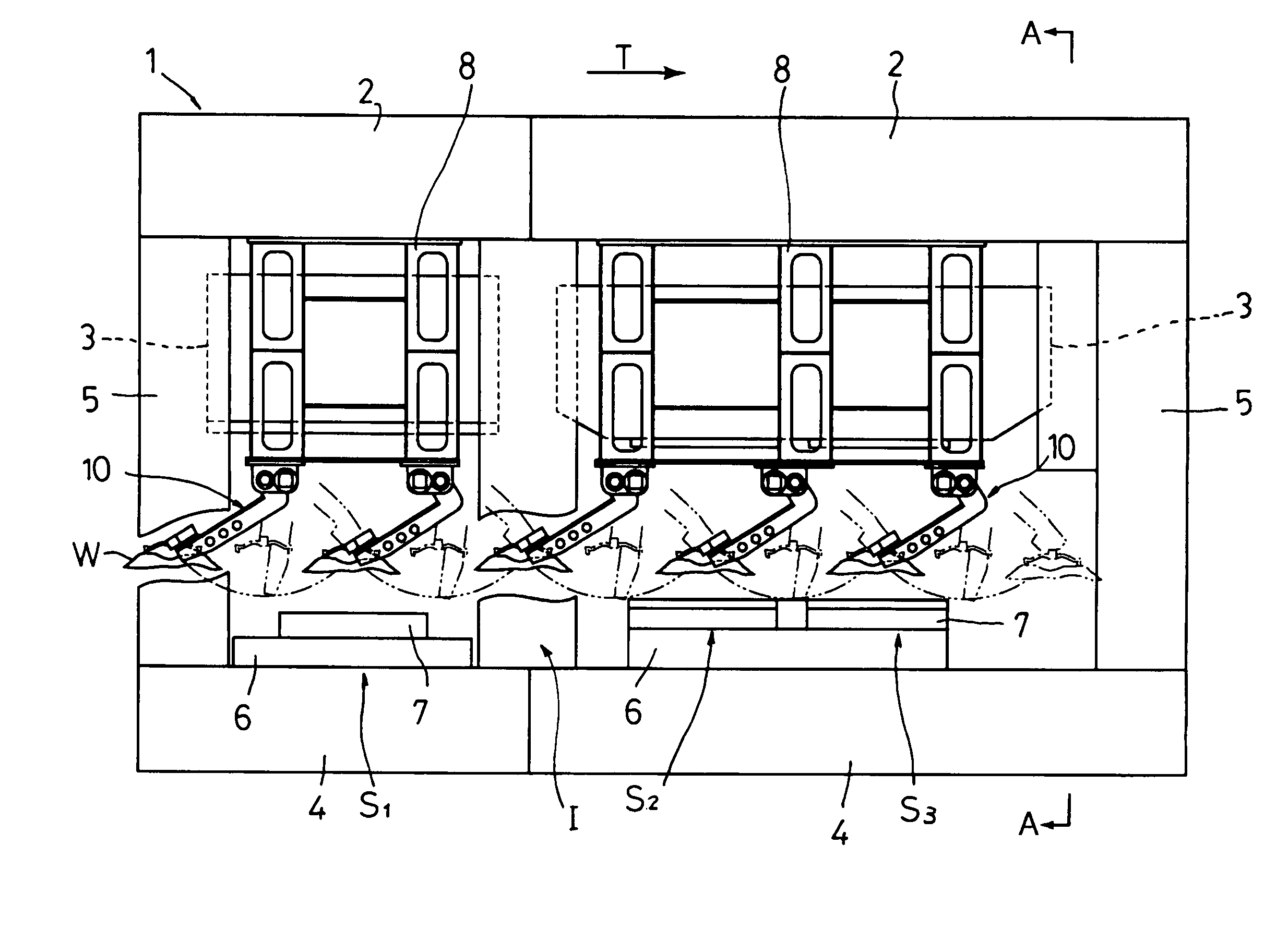
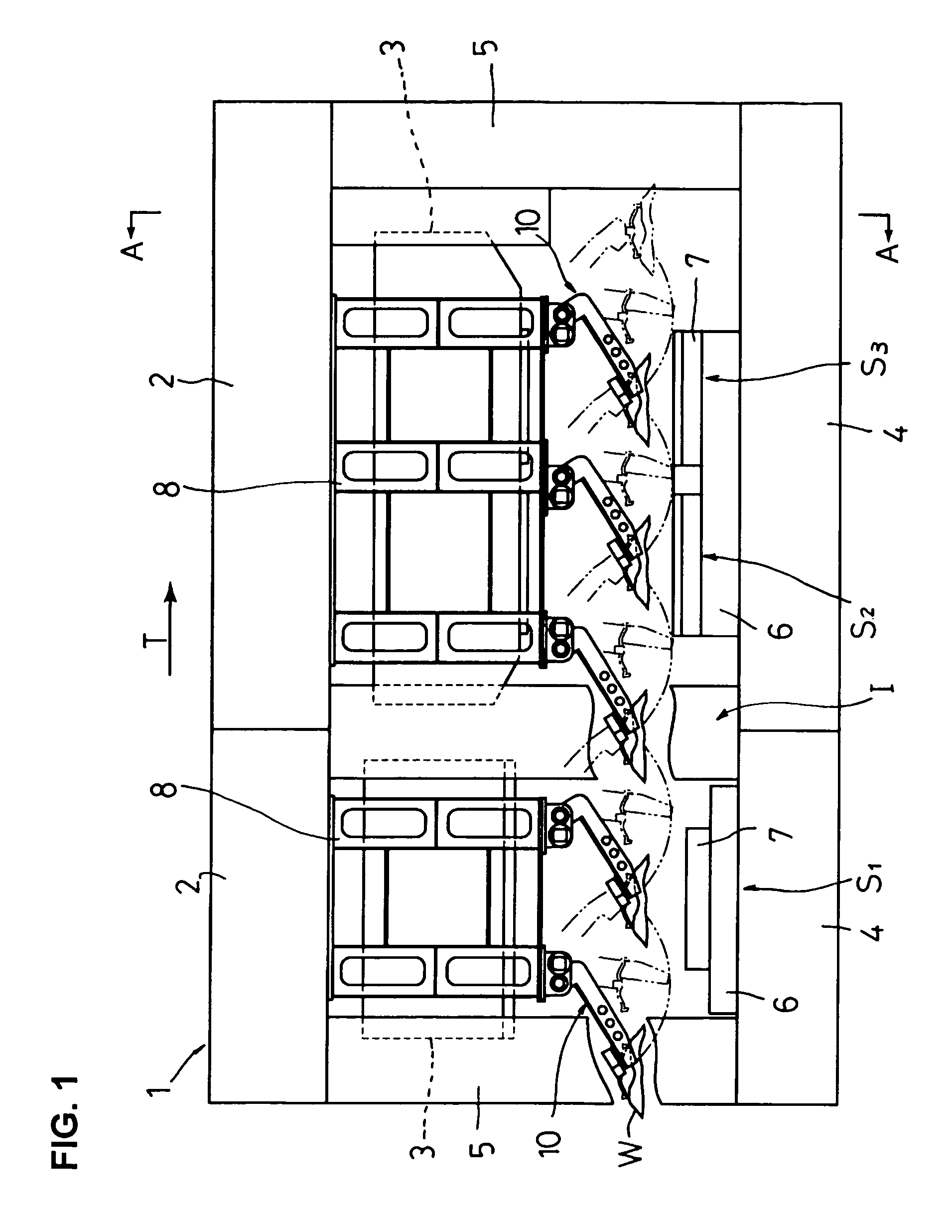
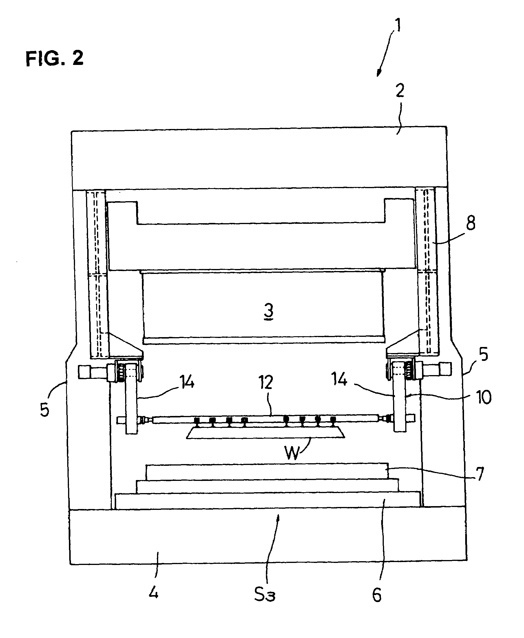
[0062]FIG. 1 shows a general schematic front view of a transfer press according to a first embodiment of the invention. FIG. 2 shows an essential part side view taken along line A—A of FIG. 1.

[0063]A transfer press 1 according to the first embodiment has crowns 2, slides 3 and beds 4. In the transfer press 1, the crowns 2, uprights 5 and the beds 4 are integrated by tie rods (not shown) and press molding is performed using an upper die (not shown) attached to the underside of each slide 3 and a lower die 7 mounted on a moving bolster 6 opposed to the slide 3. Desired work stations S1, S2, S3 and an idle station I1 are provided in compliance with a process specification, and a desired number of workpiece conveyors 10 (five workpiece conveyors in this embodiment) are disposed according to the operation for carrying a workpiece W into or out of the processing position of each of the work stations S1, S2, S3 and idle station I1. Herein, the driving mechanism of the slide 3, which is omi...

second embodiment

[0074]Next, reference is made to FIGS. 5 and 6 to describe a workpiece conveyor according to a second embodiment of the invention. FIG. 5 shows an essential part sectional and front view illustrating the structure and operation of the workpiece conveyor according to the second embodiment. FIGS. 6(a) and 6(b) show an essential part sectional and plan view and an essential part sectional and side view, respectively, of the workpiece conveyor according to the second embodiment. Similarly to the workpiece conveyor 10 of the first embodiment, a workpiece conveyor 30 of the second embodiment is bilaterally symmetrical with respect to the workpiece conveying direction T, and therefore only the right part of the workpiece conveyor 30 is illustrated in FIGS. 5 and 6 for the sake of simplicity. In the second embodiment, the parts similar to those of the first embodiment are designated by the same reference numerals as given to the first embodiment and a detailed description thereof will be om...

third embodiment

[0081]FIGS. 7(a) and 7(b) show a front view and a view taken in the direction of arrow C of FIG. 7(a), respectively, which illustrate the structure and operation of a workpiece conveyor according to a third embodiment of the invention. In FIGS. 7(a), 7(b), the parts similar to those of the foregoing embodiments are designated by the same reference numerals as given to the foregoing embodiments.

[0082]A workpiece conveyor 50 according to the third embodiment has, at one side, a first arm (rocking element) 52 the proximal end of which is pivotally attached to a clevis-type bracket 51 secured to the underside of the supporting column structural member 8; and a second arm (corresponding to “at least one link” of the invention) 53 the proximal end of which is pivotally attached to the distal end of the first arm 52. The first arm 52 is oscillating-driven relative to the bracket 51 by activation of the servo motor 20 mounted on the bracket 51 through the reduction gear 19, whereas the seco...


PUM

PropertyMeasurementUnit
degree of freedomaaaaaaaaaa
vertical distanceaaaaaaaaaa
distanceaaaaaaaaaa

Abstract

A work piece conveyor whose structure is simplified and downsized with the intention of achieving cost reduction, an improved degree of freedom in setting a motion pattern and improved productive efficiency. The workpiece conveyor is such that a cross bar carrier for supporting a cross bar provided with vacuum cups is movably attached, through a linear movement mechanism, to a feed lever which is oscillating-driven along a workpiece conveying direction, thereby making the relative distance between the center of oscillation of the rocking element and the cross bar variable.

Description

TECHNICAL FIELD[0001]The present invention relates to a workpiece conveyor incorporated in a press line for transferring workpieces into and out of work stations in synchronization with press work.BACKGROUND ART[0002]Typical press lines such as transfer presses and tandem press lines are provided with workpiece conveyors for transferring workpieces into and out of work stations in synchronization with a series of multiple press work operations.[0003]As such workpiece conveyers, there has been proposed a workpiece conveyor (transfer feeder) for use in a transfer press in Japanese Patent Kokai Publication No. 6-262280 filed by the present applicant. The workpiece conveyor 200 disclosed in this publication comprises, as shown in FIG. 24, a pair of lift beams 201 disposed side by side, extending in a workpiece conveying direction T; a plurality of cross bar carriers 202 aligned at intervals in the workpiece conveying direction T, being movably supported by these lift beams 201; cross ba...

Claims


Application Information

Patent Timeline
Patent Type & Authority Patents(United States)
IPC IPC(8): B65G47/34B23Q1/54B23Q7/04B23Q7/14
CPCB23Q1/5468B23Q7/043B23Q7/1405
Inventor YOSHIDA, TOSHIYUKIAKASHI, HIDETOSHISHIROZA, KAZUHIKO
Owner KOMATSU LTD
Why Eureka
Try Eureka