
Fuel injection system comprising a fuel-guiding component, a fuel injection valve and a mounting

a fuel injection system and fuel-guiding component technology, which is applied in the direction of noise reduction fuel injection, fuel injection apparatus, charge feed system, etc., can solve the problems of a1 being believed to have the disadvantage of vibration transmission, vibration transmission from the fuel injection valve to the connecting piece, and a1 being believed to have the disadvantage of reducing the overall noise level of the engine, so as to improve the mounting of the fuel injection valve, reduce noise, and improve the effect of noise reduction

Active Publication Date: 2016-01-07
ROBERT BOSCH GMBH
View PDF10 Cites 8 Cited by
  • Summary
  • Abstract
  • Description
  • Claims
  • Application Information

AI Technical Summary

Benefits of technology

The invention provides a mounting system for a fuel injection valve that reduces noise in the overall system. The mounting is done through a soft connection, which also helps to improve the engine's performance. This decoupling technique targets specific components to reduce noise and achieves a quieter system.

Problems solved by technology

The fuel injection device from DE 10 2005 020 380 A1 is believed to have the disadvantage that vibrations can be transmitted, via the wire ring, between the connecting piece and the inlet connector of the fuel injection valve.
Specifically, vibrations can be transmitted from the fuel injection valve to the connecting piece.
Specifically in the case of electromagnetic high-pressure injection valves that are used in gasoline engines having direct injection, a noticeable and disturbing contribution to the overall noise level of the engine can be made, which can be described as valve ticking.
This causes a strong development of noise at the cylinder head and at the fuel distributor rail.

Method used


Image

  • Fuel injection system comprising a fuel-guiding component, a fuel injection valve and a mounting
  • Fuel injection system comprising a fuel-guiding component, a fuel injection valve and a mounting
  • Fuel injection system comprising a fuel-guiding component, a fuel injection valve and a mounting

Examples


Embodiment Construction

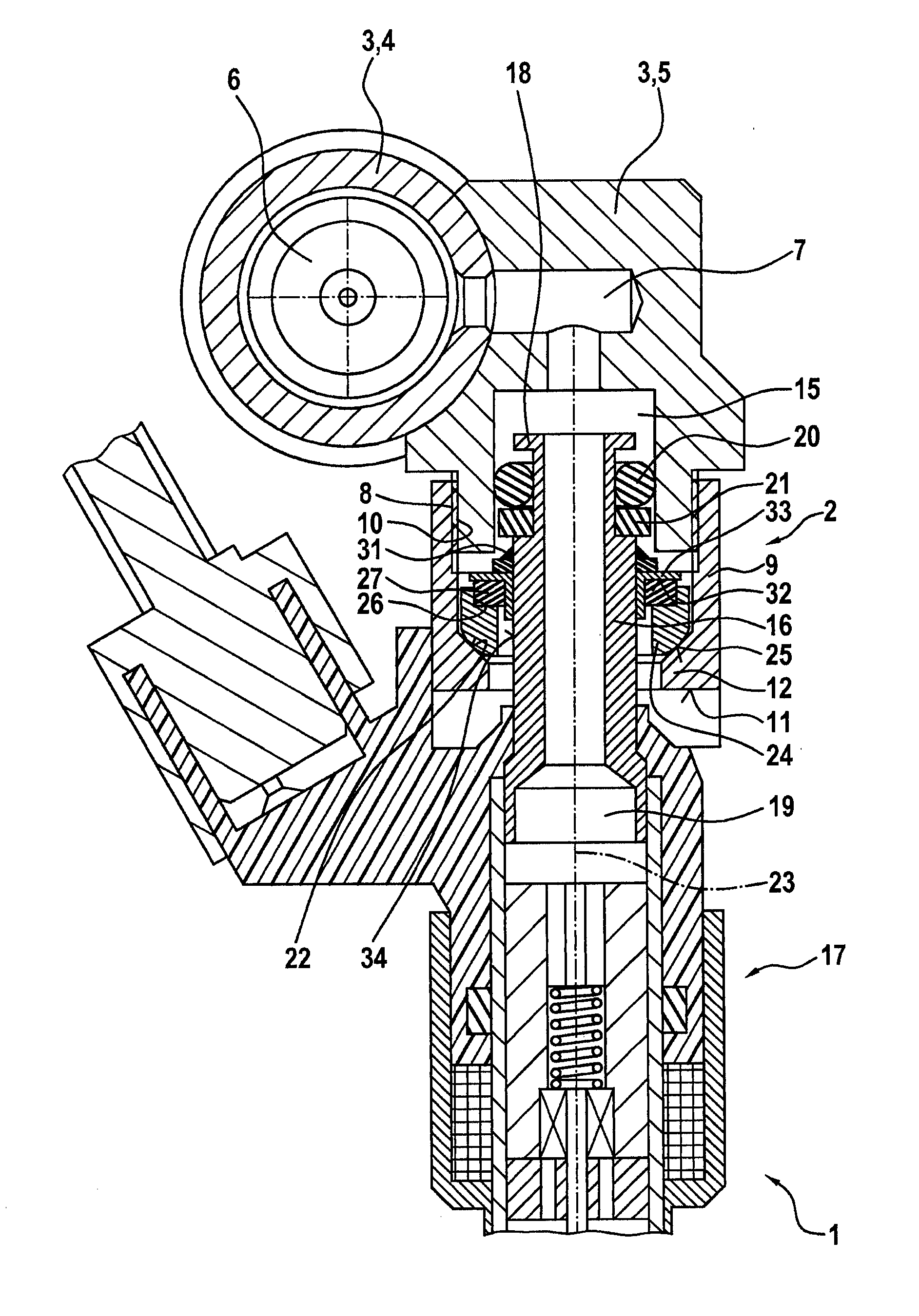
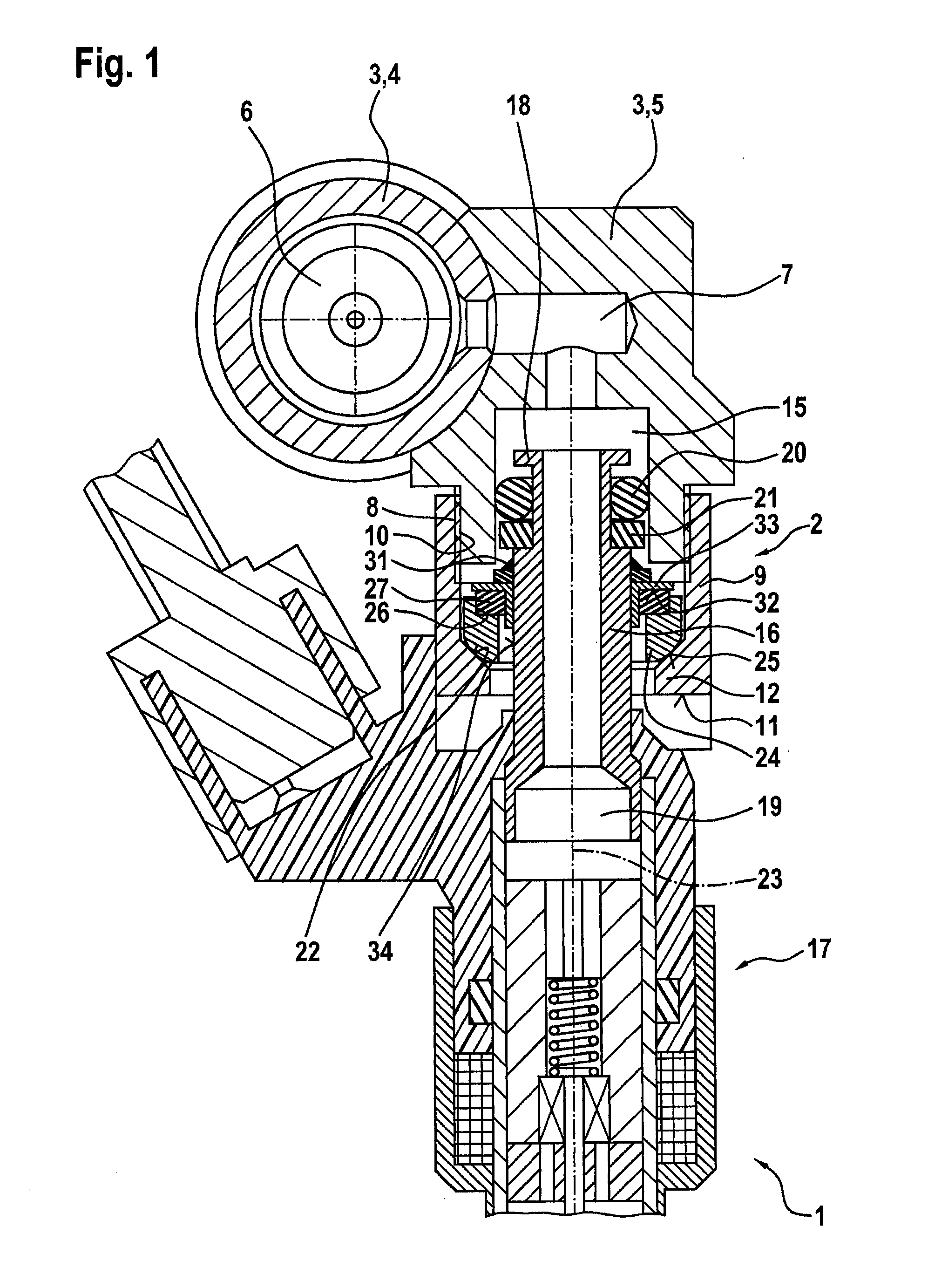
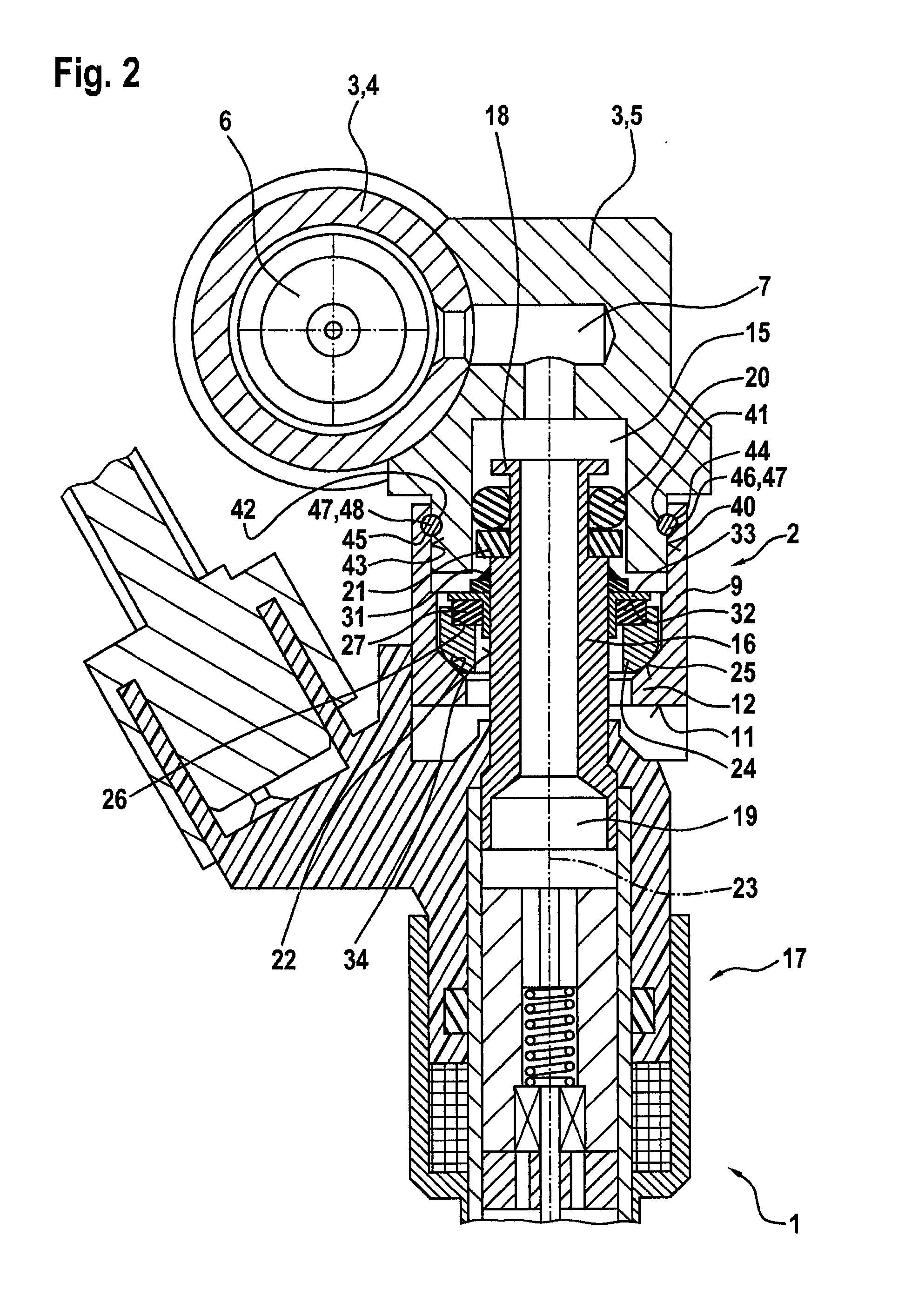
[0023]FIG. 1 shows a fuel injection system 1 having a mounting 2, in a partial schematic sectional representation corresponding to a first exemplary embodiment. Fuel injection system 1 can be used in particular for high-pressure injection in internal combustion engines. Specifically, fuel injection system 1 can be used in mixture-compressing externally ignited internal combustion engines. Mounting 2 is particularly suitable for such a fuel injection system 1.

[0024]Fuel injection system 1 has a fuel-conducting component 3 that, in this exemplary embodiment, is configured as fuel distributor rail 3. Fuel distributor rail 3 has a tube-shaped main body 4 and a connecting body 5. In tube-shaped main body 4 there is configured an oblong combustion chamber 6, from which there branches off a connecting duct 7 that is routed through connecting body 5. Here, further connecting bodies, which are configured in a manner corresponding to connecting body 5, may be attached on tube-shaped main body...


PUM


Abstract

A mounting is provided for fuel injection systems, the mounting connecting a fuel injection valve to a fuel-conducting component, and having a connecting body and a connecting piece that are connected to one another. Inside the connecting body and the connecting piece there is configured a receptacle space in which a fuel connector of the fuel injection valve is at least partly situated. An inner collar is configured on the connecting piece. In addition, an elastically deformable element is provided. The elastically deformable element is supported at least indirectly on the inner collar of the connecting piece. In addition, the fuel connector is supported at least indirectly on the elastically deformable element. In addition, a fuel injection system having such a mounting is described.

Description

FIELD OF THE INVENTION[0001]The present invention relates to a mounting for fuel injection systems for connecting a fuel injection valve to a fuel-conducting component, and to a fuel injection system having such a mounting. Specifically, the present invention relates to the area of fuel injection systems for mixture-compressing externally ignited internal combustion engines.BACKGROUND INFORMATION[0002]German patent document DE 10 2005 020 380 A1 discusses a fuel injection device having a sound-decoupling design. The fuel injection device includes a fuel injection valve, a receptacle bore for the fuel injection valve in a cylinder head, and a fuel distributor line having a connecting piece. The fuel injection valve is partly inserted into the connecting piece. In a possible embodiment, the fuel injection valve has in the region of its inlet connector a wire ring set in a groove. In addition, a connecting body is provided in the form of a locking nut that is screwed onto an outer thre...

Claims


Application Information

Patent Timeline
Patent Type & Authority Applications(United States)
IPC IPC(8): F02M61/14
CPCF02M61/14F02M2200/09F02M2200/16F02M2200/306F02M2200/853F02M2200/855F02M2200/856
Inventor REINHARDT, WILHELMSCHEEF, VOLKERMAYER, MICHAELREHWALD, ANDREASHERRMANN, JANROGLER, PHILIPPGLASER, ANDREASHORST, HANS-GEORGRIEMER, MARTINKNORPP, MICHAELFISCHER, MICHAEL
Owner ROBERT BOSCH GMBH
Learn More