Emergency Exit Route Illumination System and Methods

Inactive Publication Date: 2016-01-07
ZOZULA SONJA J
View PDF0 Cites 24 Cited by
  • Summary
  • Abstract
  • Description
  • Claims
  • Application Information

AI Technical Summary

Benefits of technology

[0032]It is a fundamental object of the present invention to overcome the obstacles and challenges of the prior art in a way that helps save lives and avoid injury by helping to orient occupants of a home, other residen

Problems solved by technology

People regularly become quickly confused and disoriented in building structures under siege by fire, smoke and other perilous situations.
In particular, when building structures are on fire or are otherwise experiencing a heavy smoke event from smoldering materials, smoke fills the building structure, floor by floor, space by space, from the ceiling down toward the floor.
In commercial settings, where “EXIT” signage is typically required, those signs are less than ideal once a fire has begun and the resulting smoke begins to quickly fill the structure.
Obviously, an “EXIT” sign above a doorway which is invisible to evacuees is relatively useless as it can no longer successfully impart the knowledge that it was intended to pass along to such evacuee(s) in the crisis due to its occlusion by the increasingly-dense smoke in the areas proximate to its installation.
Notwithstanding the safe place for such signage to be installed and to be maintained, the location is one of the worst places for its intended purpose during smoke and fire events.
But your home is also where you are most likely to die in a fire.
These fires resulted in 3,240 civilian fire fatalities, 15,925 civilian fire injuries, and an estimated $11.5 billion in direct property loss,” based on data reported to NFPA's “Fire Loss in the United States During 2013.”“Most fire deaths are not caused by burns, but by smoke inhalation.”“As a fire grows inside a building structure, it will often consume most of the available

Method used


Image

  • Emergency Exit Route Illumination System and Methods
  • Emergency Exit Route Illumination System and Methods
  • Emergency Exit Route Illumination System and Methods

Examples


Embodiment Construction

[0069]One of ordinary skill in the art can glean a good understanding of the broader inventions from consideration of several presently preferred embodiments that are depicted with the aid of FIGS. 1A-27C of the drawings, where like numerals are often used for like elements in the various embodiments. Occasional paragraph or section headings have been used for ease of reference, but such headings generally should not be read as affecting the meaning of the descriptions included in those paragraphs / sections.

[0070]Home Setting.

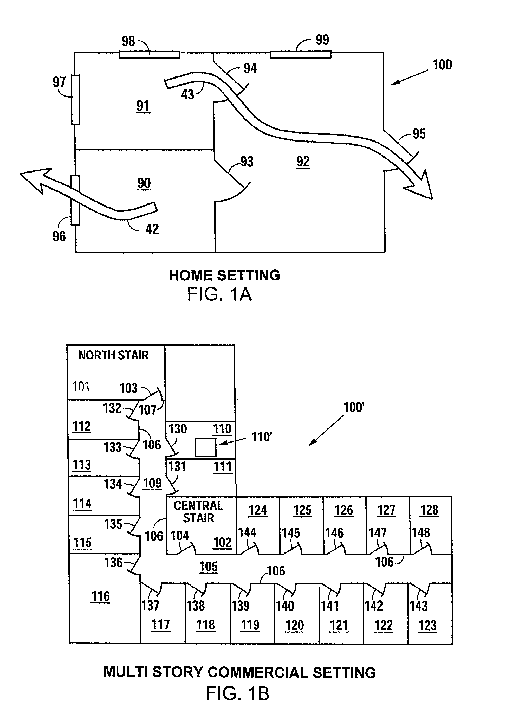
[0071]The embodiments emphasized first in this description are thought to be most applicable in the context of home settings (such as in the example of FIG. 1A) or other residential structures but may be utilized in commercial settings as well. For reference, FIG. 1A shows a simplified floor plan of a home, which is residential structure 100. The residential structure 100 depicted in FIG. 1A has two smaller rooms 90-91 and one large central room 92 with an exter...


PUM


Abstract

A system and method that helps evacuees exit a residential structure in the event of an emergency such as a fire, earthquake, security breach or the like, by providing emergency illumination around the periphery of an exit door and/or an alternative safe exit portal together with floor/ground level illumination along the path to the portal, and by providing an audible tone or voice recording to guide occupants to the exit portal. Various forms of linear illuminators parallel to and near the floor of an interior room or hallway provide the floor-level identification and illumination of the exit route to be used in the event of emergency, with some linear illuminators having directional aspects along hallways to lead evacuees toward an exit, and other illuminators outlining the perimeter of portals that are safe to exit through, the illuminators normally being hardly noticeable but having controllers and energizers to light up the planned exit route when emergency conditions are detected.

Description

CROSS-REFERENCE TO RELATED APPLICATION[0001]This application is a Continuation-in-Part of International Application No. PCT / US2014 / 058416, filed Sep. 30, 2014, entitled “Emergency Exit Route Illumination System and Methods,” which claims the benefit of the filing date of U.S. Provisional Application Ser. No. 61 / 884,485, filed Sep. 30, 2013, entitled “Modular Emergency Exit Route Illumination System and Methods.” This application is also a Continuation-in-Part of U.S. Non-Provisional application Ser. No. 14 / 633,194, filed Feb. 27, 2015, entitled “Modular Emergency Exit Route Illumination System and Methods,” which is a Divisional application of U.S. Non-Provisional application Ser. No. 13 / 763,160, filed Feb. 8, 2013, entitled “Modular Emergency Exit Route Illumination System and Method,” which is a Continuation of U.S. Non-Provisional patent application Ser. No. 13 / 011,878, filed Jan. 22, 2011, entitled “Modular Emergency Exit Route Illumination System and Methods,” all of which clai...

Claims


Application Information

Patent Timeline
IPC IPC(8): F21S8/00F21S9/02
CPCF21S9/024F21S8/033F21S4/26F21S8/032F21Y2115/10G08B7/062G08B7/066G08B17/10
Inventor ANDERSON, JERRY TZOZULA, SONJA K
Owner ZOZULA SONJA J
Why Eureka
Try Eureka