
Travel path identification based upon statistical relationships between path costs

a technology of path cost and statistical relationship, applied in the direction of navigation instruments, traffic control systems, instruments, etc., can solve the problems of difficulty in ascertaining the weight to assign to the edge, not having granular information about the entirety of the terrain, and not having granular information about the entire terrain

Active Publication Date: 2016-01-07
MICROSOFT TECH LICENSING LLC
View PDF16 Cites 26 Cited by
  • Summary
  • Abstract
  • Description
  • Claims
  • Application Information

AI Technical Summary

Benefits of technology

The patent describes a computer-based method for updating cost information in a graph based on travel segments and statistical relationships between them. This allows for the output of a suggestion for the best travel route based on the cost distribution over each edge in the graph. Essentially, the method helps to optimize travel plans based on real-time data and statistical analysis.

Problems solved by technology

A problem faced by many travelers in the physical world relates to choosing a route between a source location and destination location.
There are many analogous applications, however, where it is difficult to ascertain weights to assign to edges in the graph prior to acquiring observations for these edges.
For instance, the robot may have rough information about treacherous regions of the terrain that would risk slowing the robot, but may not have granular information about the entirety of the terrain.
Wind forecasts available for flight planning have conventionally been limited to the use of relatively coarse information, where wind speed and direction are detected by sparsely situated weather balloons.
Due to sparseness of sensors in the region, however, exact wind information is unavailable for many of the travel segments—thus, wind information for a travel segment may be unknown prior to an airplane traversing the segment.
While this conventional approach is well-suited for applications where a large amount of sensor data has been collected and weights of edges are generally known, this approach is not particularly well-suited for identifying optimal routes in a region where collected data is somewhat sparse (and possibly subject to rapid change, such as wind speed and direction, water current speed and direction, etc.).

Method used


Image

  • Travel path identification based upon statistical relationships between path costs
  • Travel path identification based upon statistical relationships between path costs
  • Travel path identification based upon statistical relationships between path costs

Examples


Embodiment Construction

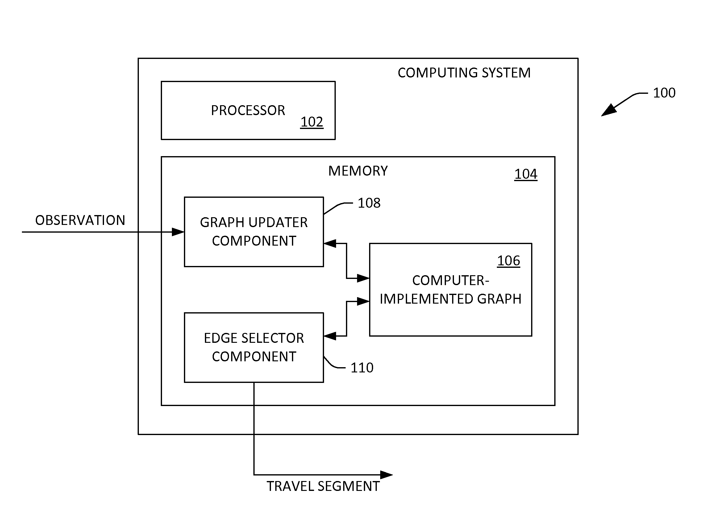
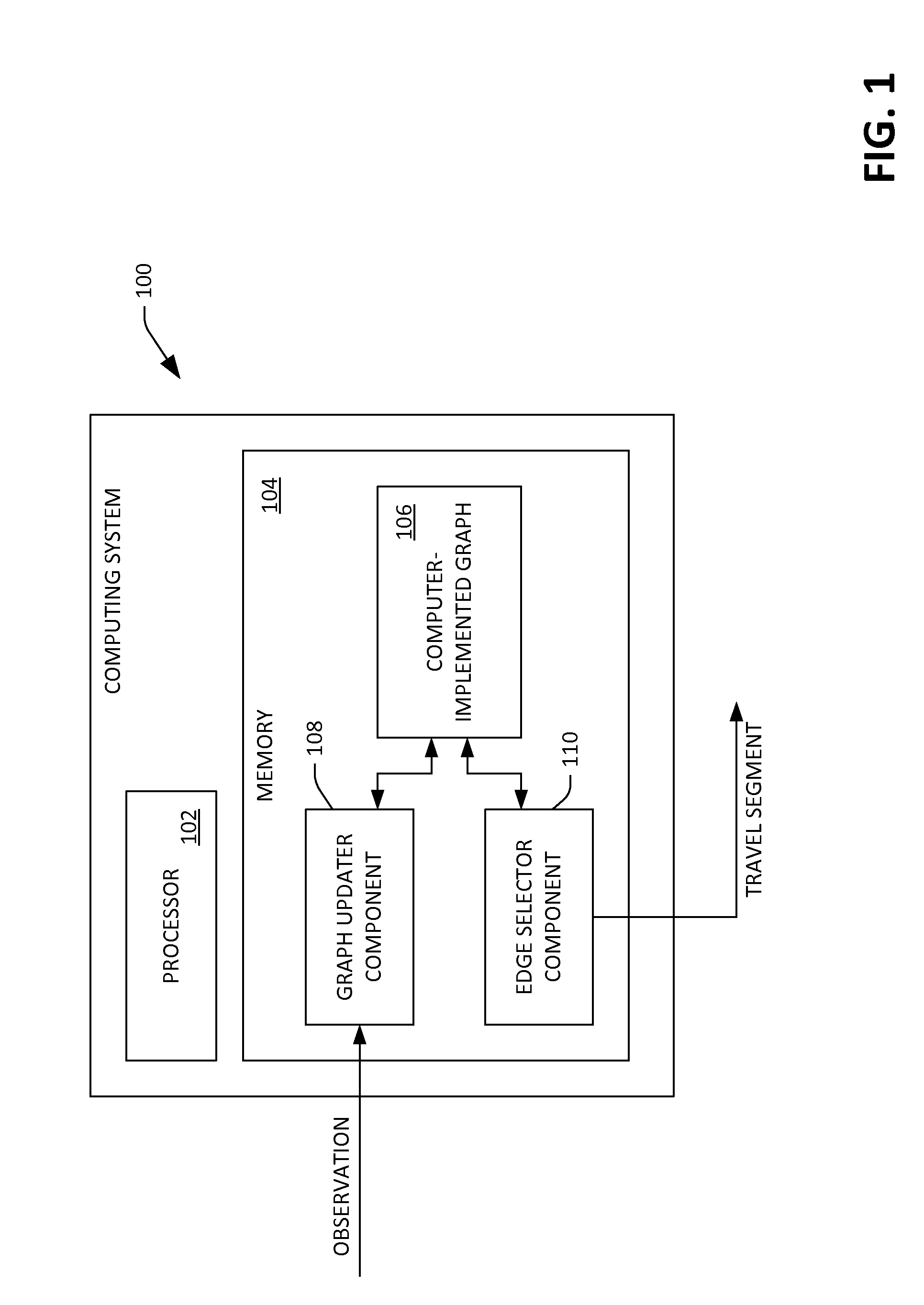
[0018]Various technologies pertaining to dynamically computing travel routes are now described with reference to the drawings, wherein like reference numerals are used to refer to like elements throughout. In the following description, for purposes of explanation, numerous specific details are set forth in order to provide a thorough understanding of one or more aspects. It may be evident, however, that such aspect(s) may be practiced without these specific details. In other instances, well-known structures and devices are shown in block diagram form in order to facilitate describing one or more aspects. Further, it is to be understood that functionality that is described as being carried out by certain system components may be performed by multiple components. Similarly, for instance, a component may be configured to perform functionality that is described as being carried out by multiple components.

[0019]Moreover, the term “or” is intended to mean an inclusive “or” rather than an ...


PUM


Abstract

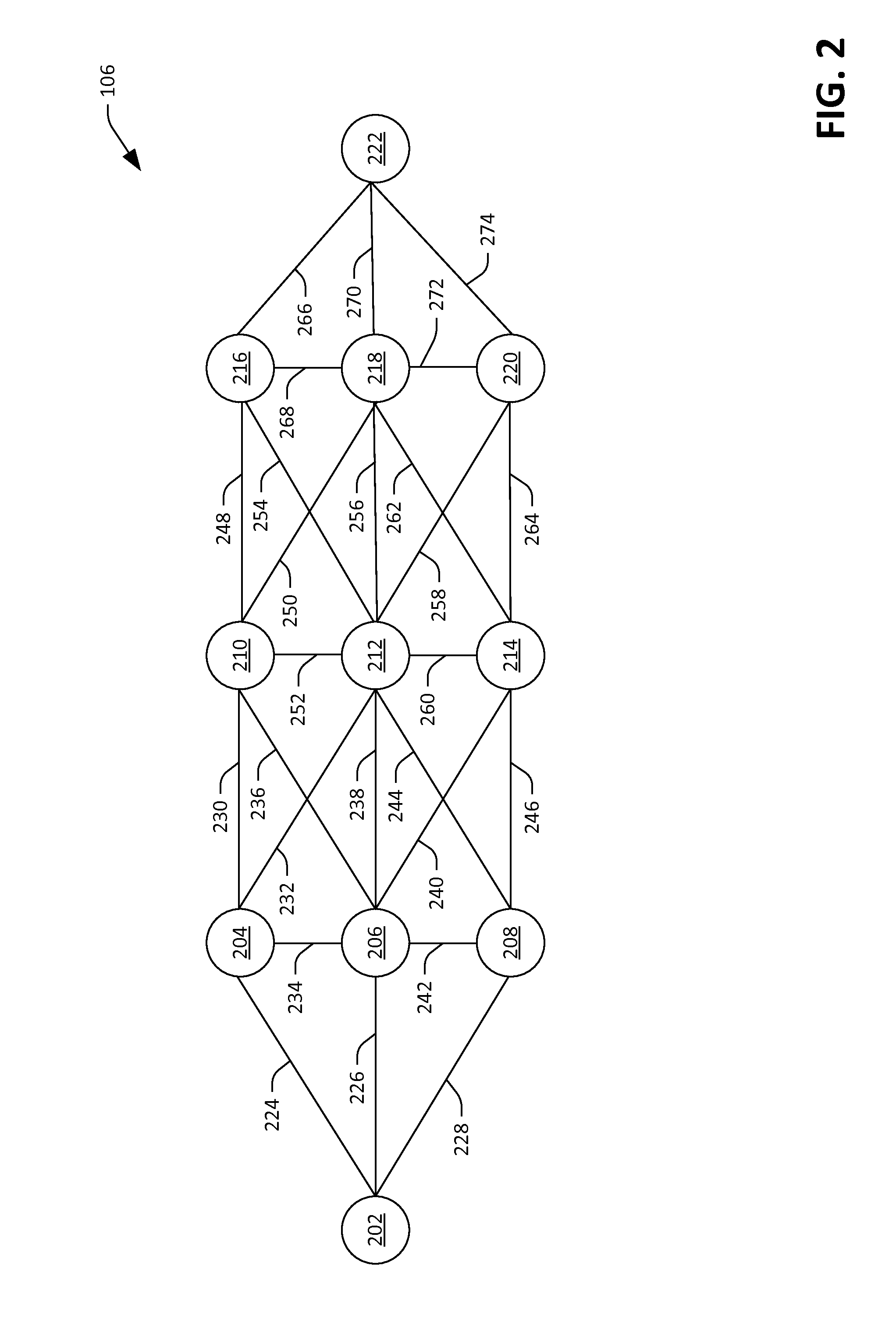
Various technologies pertaining to dynamically identifying travel segments to be taken by a traveler traveling in a region are described herein, where observations about travel segments in the region are sparse and subject to alteration. A computer-implemented graph can be loaded into a memory, where the computer-implemented graph is representative of the region. The computer-implemented graph includes nodes that represent locations in the region and edges that represent travel segments of the region, where the edges have costs assigned thereto, and further where there is a defined statistical relationship between the costs. When an observation about a travel path is received, using the computer-implemented graph, inferences can be made about costs of traversing other travel paths in the region.

Description

BACKGROUND[0001]A problem faced by many travelers in the physical world relates to choosing a route between a source location and destination location. Several computer-implemented applications have been developed to assist travelers in making such choice. For example, computer-executable applications have been developed to identify a travel route between specified source and destination locations. These computer-executable applications utilize a graph to represent a road network, where road segments are represented by respective weighted edges. A weight assigned to an edge can be indicative of, for example, the expected amount of time it will take to travel over a road segment represented by the edge (e.g., which may be a function of a speed limit assigned to the road segment, expected traffic over the road segment, or a observed traffic over the road segment). The computer-executable application searches the graph for the route between the source location and the destination locat...

Claims


Application Information

Patent Timeline
IPC IPC(8): G01C21/00
CPCG01C21/00G01C21/20G01C21/3446G08G5/0039G06Q10/047G08G1/096827G08G1/096844G08G5/0008G08G5/0021G08G5/0078G08G5/0091
Inventor KAPOOR, ASHISHDEY, DEBADEEPTAKOLOBOV, ANDREYEDEN, SEMIHA ECE KAMARCARUANA, RICHARDHORVITZ, ERIC
Owner MICROSOFT TECH LICENSING LLC
Learn More