Obversely and reversely pluggable connector structure

Active Publication Date: 2016-01-07
KUANG YING COMPUTER EQUIP CO LTD
View PDF1 Cites 24 Cited by
  • Summary
  • Abstract
  • Description
  • Claims
  • Application Information

AI Technical Summary

Benefits of technology

[0007]The main object of the present invention is to provide an obversely and reversely pluggable connector structure, using first and second transmission conductor sets different in length respectively configured on the upper and lower sides of a circuit board together to clamping and fixing a connector thereto, configuring components such as soldering faces, through holes, a shielding shell, a capacitor unit and conduction portions correspondingly on each transmission conductor set so as to complete the obversely and reversely pluggable connector, having the advantages of easy assembly, small volume and low interference.
[0008]To achieve the above object, the present invention mainly includes a first transmission conductor set configured on one side of the circuit board, a plurality of first soldering faces defined on the circuit board correspondingly to the first transmission conductor set, a plurality of first conduction portions configured on circuit board far away from inner layers of the first soldering faces, a plurality of through holes respectively configure

Problems solved by technology

Although non-directional connectors are available in the market, they are not accepted by people or manufacturers, the reasons are approximately the followings:1. the soldering of a connector and PCB (printed circuit board) can only be carried out by means of a process such as double-face DIP or one-face DIP, one-

Method used


Image

  • Obversely and reversely pluggable connector structure
  • Obversely and reversely pluggable connector structure
  • Obversely and reversely pluggable connector structure

Examples


Embodiment Construction

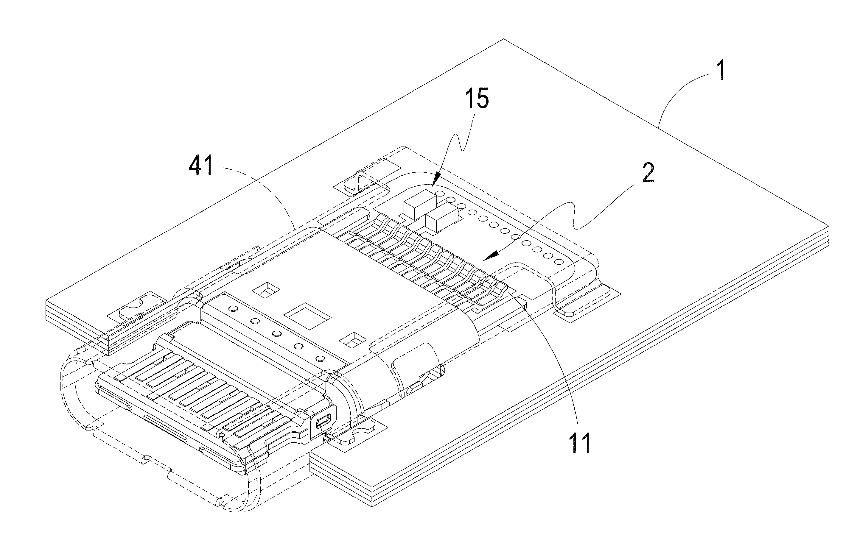
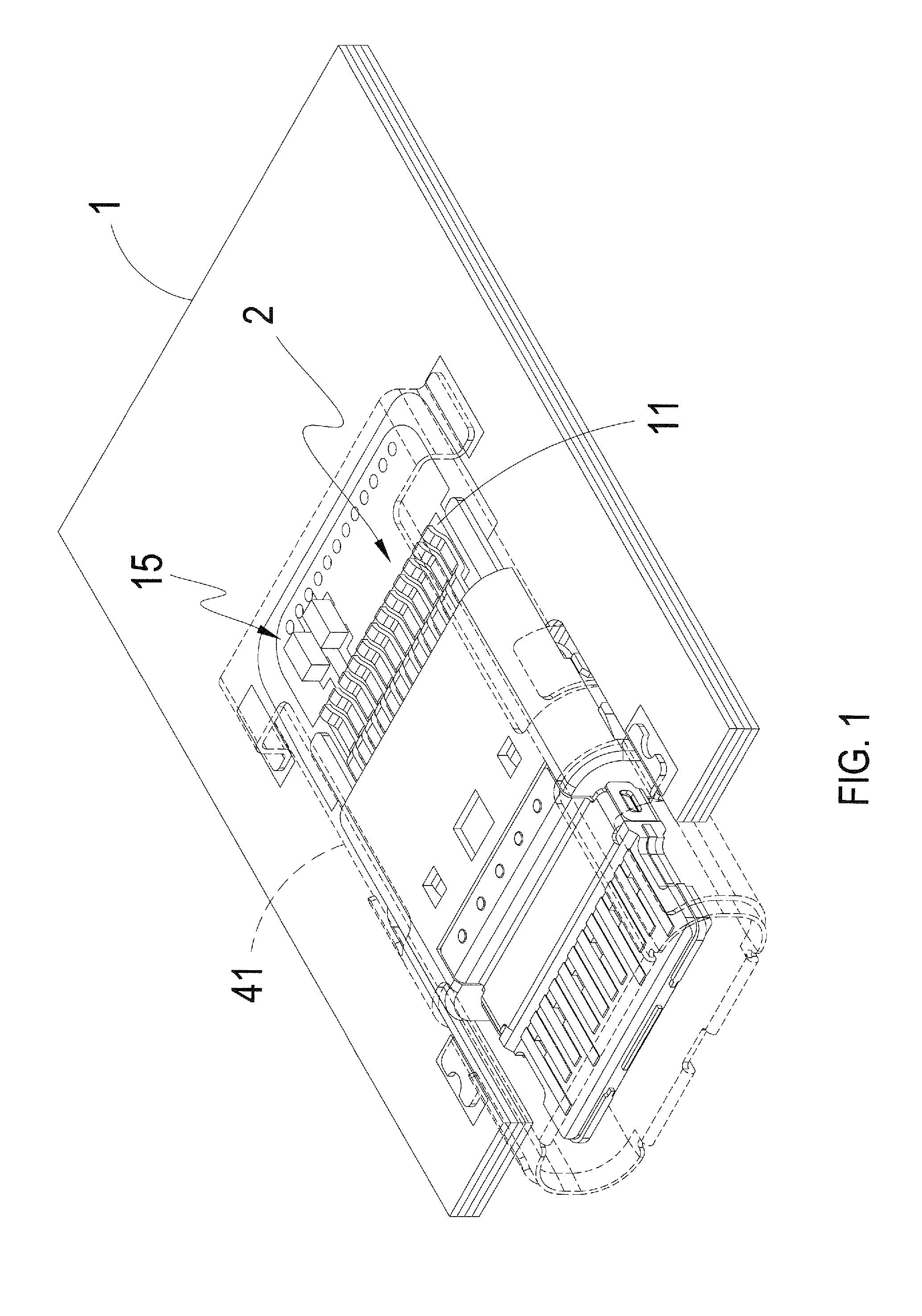
[0022]Referring to FIGS. 1 to 5, a obversely and reversely pluggable connector structure of the present invention includes:

[0023]a circuit board 1;

[0024]a first transmission conductor set 2, configured on one side of the circuit board 1;

[0025]a plurality of soldering faces 11, defined on the circuit board 1 correspondingly to the first transmission conductor set 2;

[0026]a first shielding shell 41, adapted to accommodate the first transmission conductor set 2;

[0027]at least one first capacitor unit 15, configured on the circuit board 1 and accepted inside the first shielding shell 41, the first capacitor unit 15 being positioned on one side of the first soldering face 11;

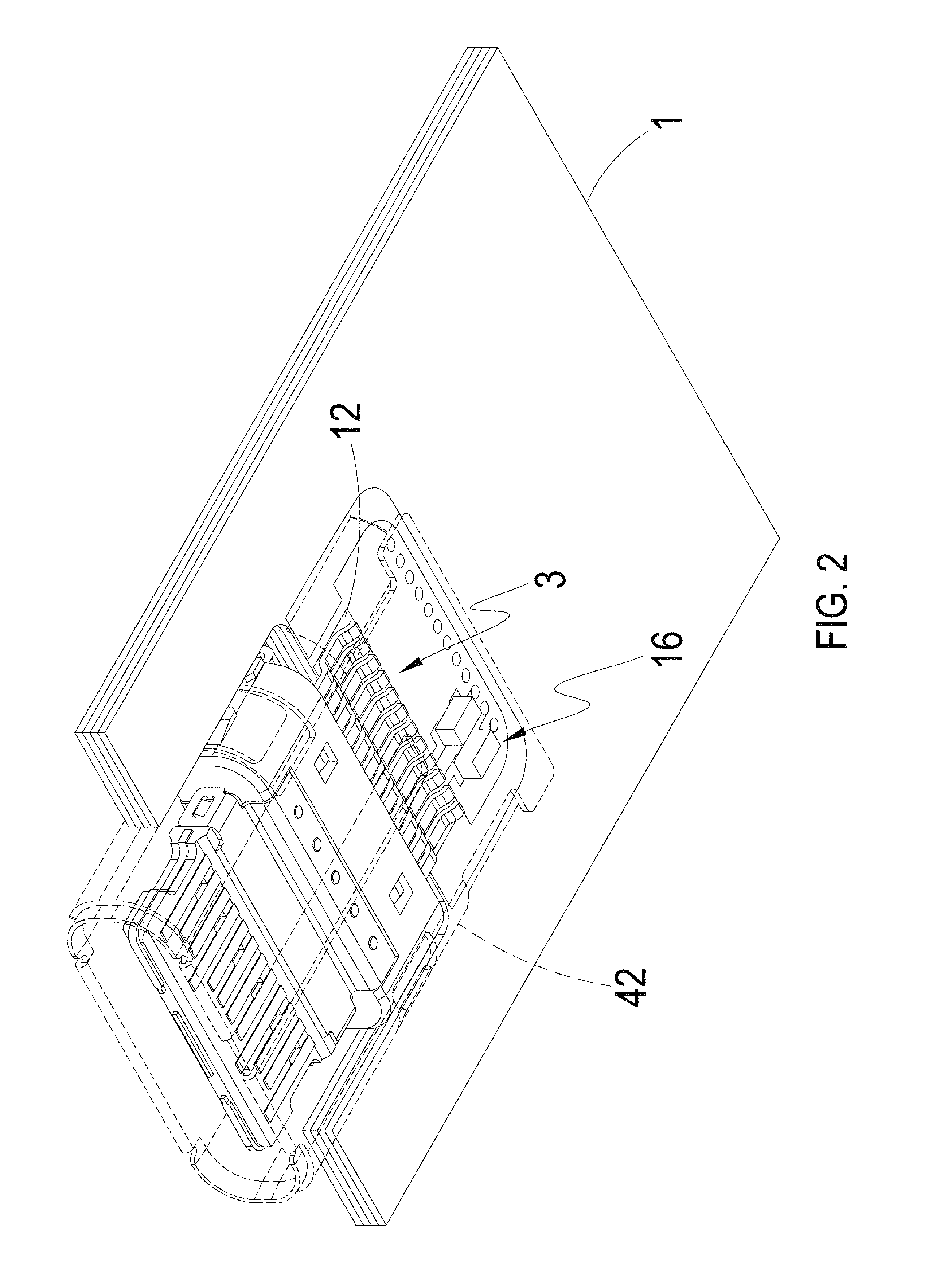
[0028]a second transmission conductor set 3, configured on another side of the circuit board 1 far away from the first transmission conductor set 2, the second transmission conductor set 2 being smaller than the first transmission conductor set 2 in length, and the connector being clamped to the circuit board 1 throu...


PUM


Abstract

An obversely and reversely pluggable connector structure, includes a multi-plate circuit board, first transmission conductor set and second transmission conductor set each, a plurality of first soldering faces and second soldering faces, a plurality of first conduction portions and second conduction portions, a plurality of first through holes and second through hole portions, a first shielding shell and second shielding shell each, first capacitor unit and second capacitor unit each at least, allowing the first transmission conductor set and second transmission conductor set different in length to clamp a connector to the circuit board together through the above components, and components for soldering, conducting, reducing noise are configured correspondingly to each transmission conductor set, thereby achieving the reduction of the volume upon a connector assembly, and having the effect of decreasing EMI (Electromagnetic interference) and RFI (radio frequency interference).

Description

TECHNICAL FIELD OF THE INVENTION[0001]The present invention relates to an obversely and reversely pluggable connector structure, and more particularly to an obversely and reversely pluggable connector structure, capable of clamping and fixing a connector from the upper side and lower side of a circuit board, reducing the volume after the assembly is completed, and having a noise restraining function.DESCRIPTION OF THE PRIOR ART[0002]The use of connectors is fully universal with respect to the current technologies. No matter what kind of connector, for example, universal serial bus (USB), micro-USB or mini-USB, it is, to avoid reverse plugging, the opposite joint direction of male and female contacts must always be affirmed before plugging, or the deformation of male and female contacts or the damage of substrates is caused easily due to the reverse plugging.[0003]Although non-directional connectors are available in the market, they are not accepted by people or manufacturers, the re...

Claims


Application Information

Patent Timeline
IPC IPC(8): H01R13/6581H01R12/51
CPCH01R13/6581H01R12/51H01R12/725H01R13/6594
Inventor CHUNG, HSUAN-HOLIN, YU-HUNGCHUNG, WEI-PANGLI, KUANG-SHANCHIANG, YUAN-CHIN
Owner KUANG YING COMPUTER EQUIP CO LTD
Why Eureka
Try Eureka