Image processing device and method for operating endoscope system

Active Publication Date: 2016-01-07
FUJIFILM CORP
View PDF3 Cites 1 Cited by
  • Summary
  • Abstract
  • Description
  • Claims
  • Application Information

AI Technical Summary

Benefits of technology

[0017]According to the present invention, even in the case where the capillary vessels and the microstructure are separately diagnosed, it is possible to generate an endos

Problems solved by technology

In the recent “VS classification”, it has become clear that the existence of the blood vessels hinders accurate diagnoses of the microstructure in performing diagnoses based on observation of the microstructure.
In such a case, possibility of misdiagnosis is increased.
Although United States Patent Application Publication No. 2012/0197076 discloses selective enhancement/suppression of the display of the superficial blood vessels and the deep blood vessels, United States Patent Application Publication No. 2012/0197076 does not

Method used


Image

  • Image processing device and method for operating endoscope system
  • Image processing device and method for operating endoscope system
  • Image processing device and method for operating endoscope system

Examples


first embodiment

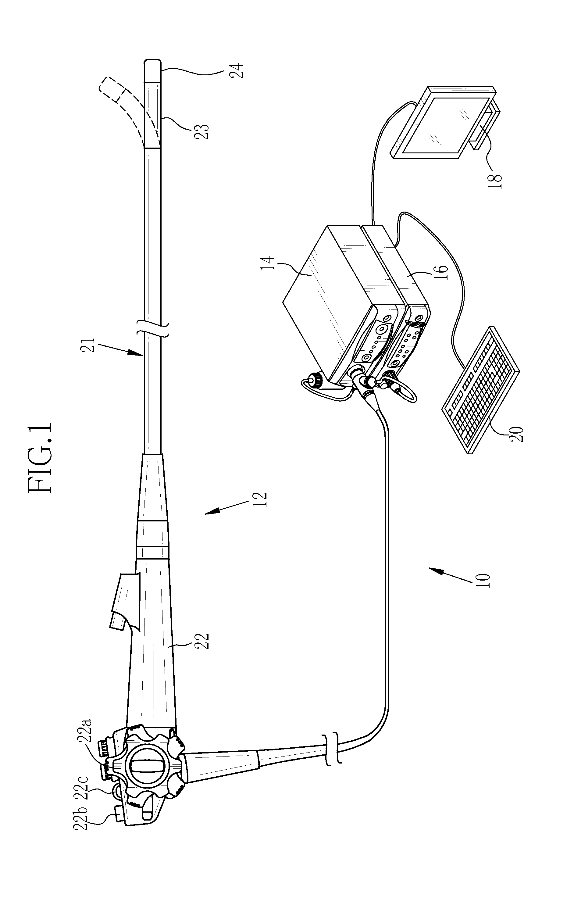
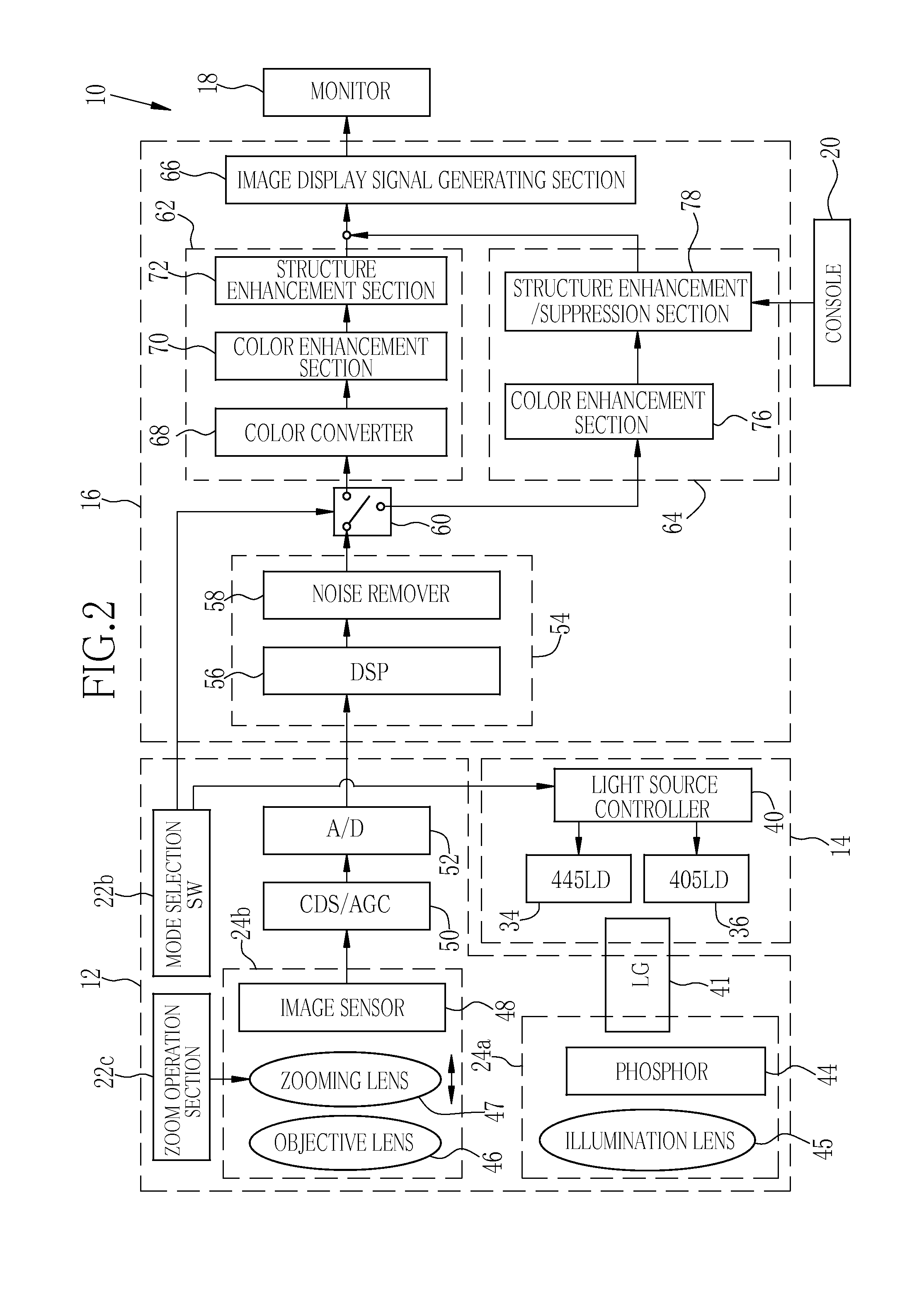
[0040]As shown in FIG. 1, an endoscope system 10 according to a first embodiment of the present invention includes an endoscope 12, a light source device 14, a processor device 16, a monitor 18, and a console 20. The endoscope 12 is optically connected to the light source device 14, and is electrically connected to the processor device 16. The endoscope 12 has an insert section 21, a handle section 22, a bending portion 23, and a distal portion 24. The insert section 21 is inserted into an observation object. The handle section 22 is provided in a proximal portion of the insert section 21. The bending portion 23 and the distal portion 24 are provided on a distal side of the insert section 21. The bending portion 23 is bent by operating an angle knob 22a of the handle section 22. The bending portion 23 is bent to direct the distal portion 24 to a desired direction.

[0041]In addition to the angle knob 22a, the handle section 22 is provided with a mode selection SW (switch) 22b and a zo...

second embodiment

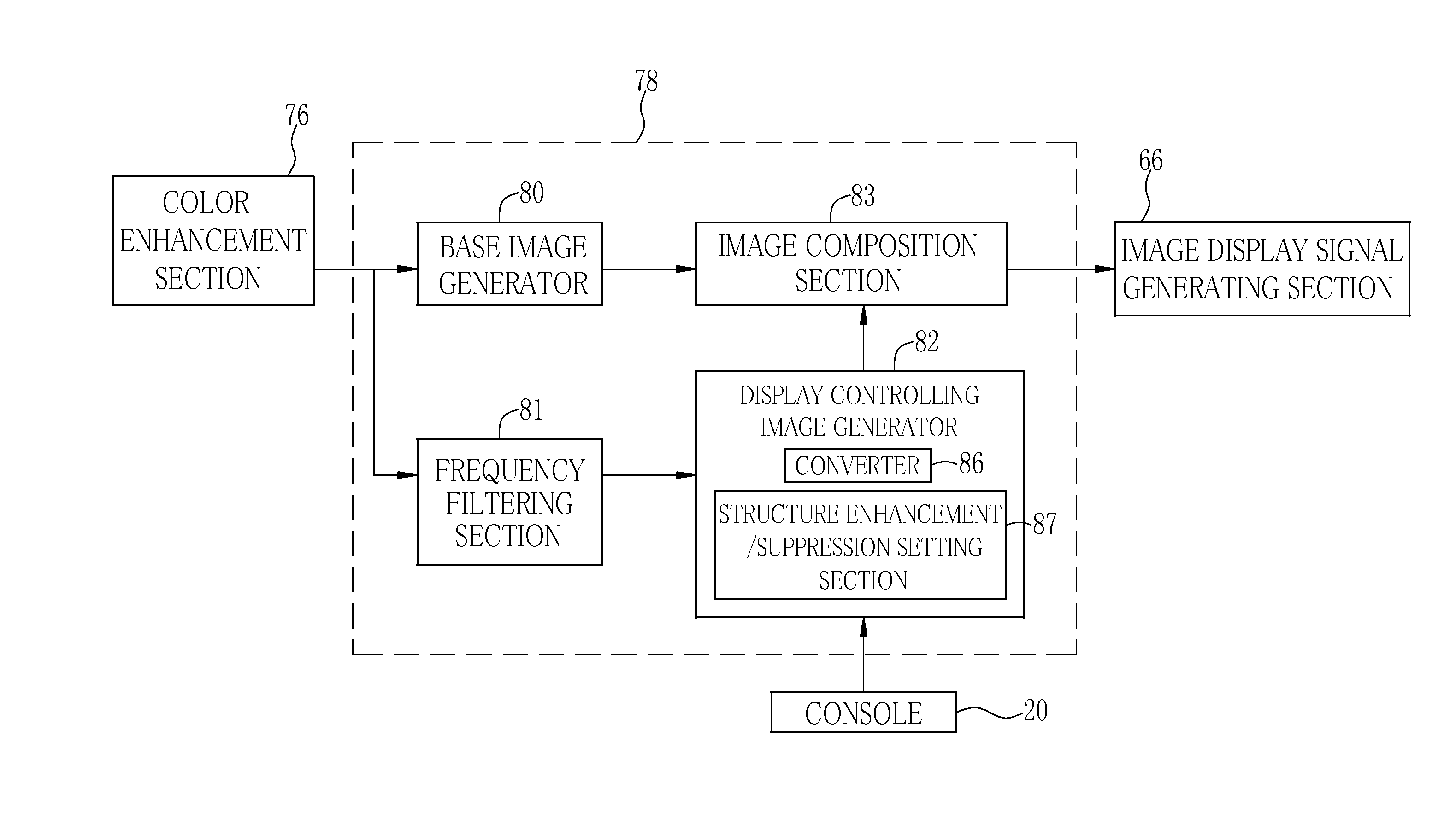
[0084]In the first embodiment, both the ductal structure S and the capillary vessels V are extracted by performing the frequency filtering process on the B image signal. In the second embodiment, the ductal structure S and the capillary vessels V are separately extracted by separately performing a frequency filtering process for ductal structure extraction on the B image signal and a frequency filtering process for blood vessel extraction on the B image signal. In light of the fact that the frequency band of the capillary vessels V is slightly closer to a high-frequency band in comparison with the frequency band of the ductal structure S, it is preferable that the frequency filtering process for ductal structure extraction and the frequency filtering process for blood vessel extraction are separately performed on the B image signal as with the second embodiment.

[0085]In a structure enhancement / suppression section 130 of the second embodiment shown in FIG. 16, instead of the frequenc...

third embodiment

[0087]In the first embodiment, the display controlling image is combined with the base image so as to enhance / suppress the display of the ductal structure S and the display of the capillary vessels V. In the third embodiment, the display controlling image is combined with the base image so as to enhance the display of the ductal structure S or the display of the capillary vessels V, however, the base image is subjected to a blurring process so as to suppress the display of the ductal structure S or the display of the capillary vessels V.

[0088]In a structure enhancement / suppression section 140 of the third embodiment shown in FIG. 17, a suppression processing section 142 for blurring the base image is disposed between the base image generator 80 and the image composition section 83. Further, instead of the display controlling image generator 82 of the first embodiment, a display controlling image generator 144 for generating a display controlling image is disposed. Furthermore, the s...


PUM


Abstract

A base image includes a B image signal in which ductal structure is brighter than mucous membrane and capillary vessels are darker than the mucous membrane. The B image signal is subjected to a frequency filtering process for extracting frequency components including the ductal structure and the capillary vessels. Thereby, a structure-extracted image signal, in which a pixel value of the ductal structure is a positive value and a pixel value of the capillary vessels is a negative value, is generated. Based on the structure-extracted image signal, a display controlling image to be used for enhancing display of the ductal structure and suppressing display of the capillary vessels is generated. The base image is combined with the display controlling image to obtain a display-controlled image in which the display of the ductal structure is enhanced and the display of the capillary vessels is suppressed.

Description

CROSS-REFERENCE TO RELATED APPLICATIONS[0001]This application is a Continuation of PCT International Application No. PCT / JP2014 / 052247 filed on Jan. 31, 2014, which claims priority under 35 U.S.C §119 (a) to Japanese Patent Application No. 2013-037782 filed Feb. 27, 2013. The above application is hereby expressly incorporated by reference, in its entirety, into the present application.BACKGROUND OF THE INVENTION[0002]1. Field of the Invention[0003]The present invention relates to an image processing device and a method for operating an endoscope system, for performing diagnoses based on observation of a ductal structure and capillary vessels.[0004]2. Description Related to the Prior Art[0005]Diagnoses using endoscope systems are widely performed in current medical care. The endoscope system includes a light source device, an electronic endoscope, and a processor device. Observation of an inside of an observation object is performed using the endoscope system. Such observation includ...

Claims


Application Information

Patent Timeline
IPC IPC(8): H04N9/04A61B1/04G06K9/46H04N5/225H04N5/232H04N5/262H04N5/265H04N9/79
CPCH04N9/04A61B1/04H04N5/23293H04N5/265G06K9/4652H04N5/2256H04N5/2628G06K9/46H04N9/7908G02B23/2484G02B23/26A61B1/0005A61B1/000094A61B1/044H04N23/555H04N23/56H04N23/631H04N23/10
Inventor KURAMOTO, MASAYUKI
Owner FUJIFILM CORP
Why Eureka
Try Eureka