
Method of controlling bandwidth in an always on video conferencing system

a video conferencing and bandwidth control technology, applied in the field of video conferencing, can solve the problems of frequent connection via a wireless network on which bandwidth may be either expensive or limited, video has been known for a considerable period, and expensive “nailed” up connections have been employed, etc., to achieve the effect of reducing frame rate, reducing bitrate, and substantially reducing video bandwidth

Inactive Publication Date: 2016-01-07
MAGOR COMM CORP
View PDF3 Cites 19 Cited by
  • Summary
  • Abstract
  • Description
  • Claims
  • Application Information

AI Technical Summary

Benefits of technology

The patent describes a method for reducing the amount of video data transmitted in video conferencing systems, by detecting the absence of certain features in the received video and adjusting the quality of the video accordingly to reduce traffic on the network. This can save money and improve the quality of video calls, while also improving the performance of other applications that may be using the network. The method involves sending metadata about the video frame content to the receiver, which can then adjust its quality based on the absence of certain features. This enables better video quality when needed, while reducing communication costs. Overall, the method provides an efficient and effective way to manage video data in video conferencing systems.

Problems solved by technology

Although Internet connections with sufficient bandwidth are increasingly common, making the always-on concept practical, devices frequently connect via a wireless network on which bandwidth may be either expensive or limited or both.
The concept of spontaneous or always-on video has been known for a considerable period of time and expensive “nailed” up connections have been employed.

Method used


Image

  • Method of controlling bandwidth in an always on video conferencing system
  • Method of controlling bandwidth in an always on video conferencing system
  • Method of controlling bandwidth in an always on video conferencing system

Examples


Embodiment Construction

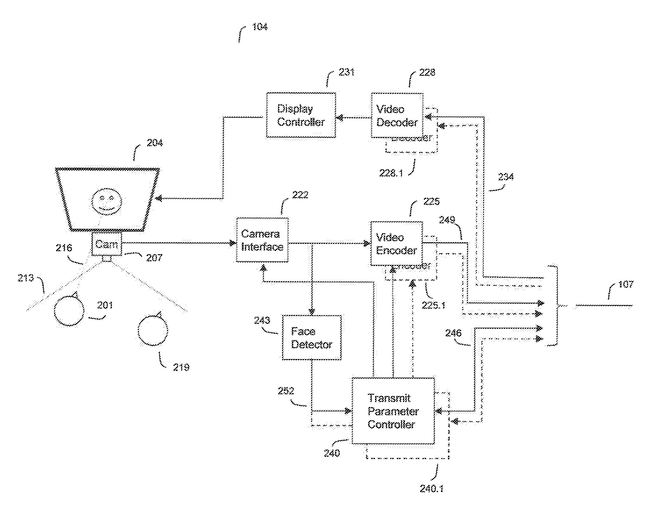
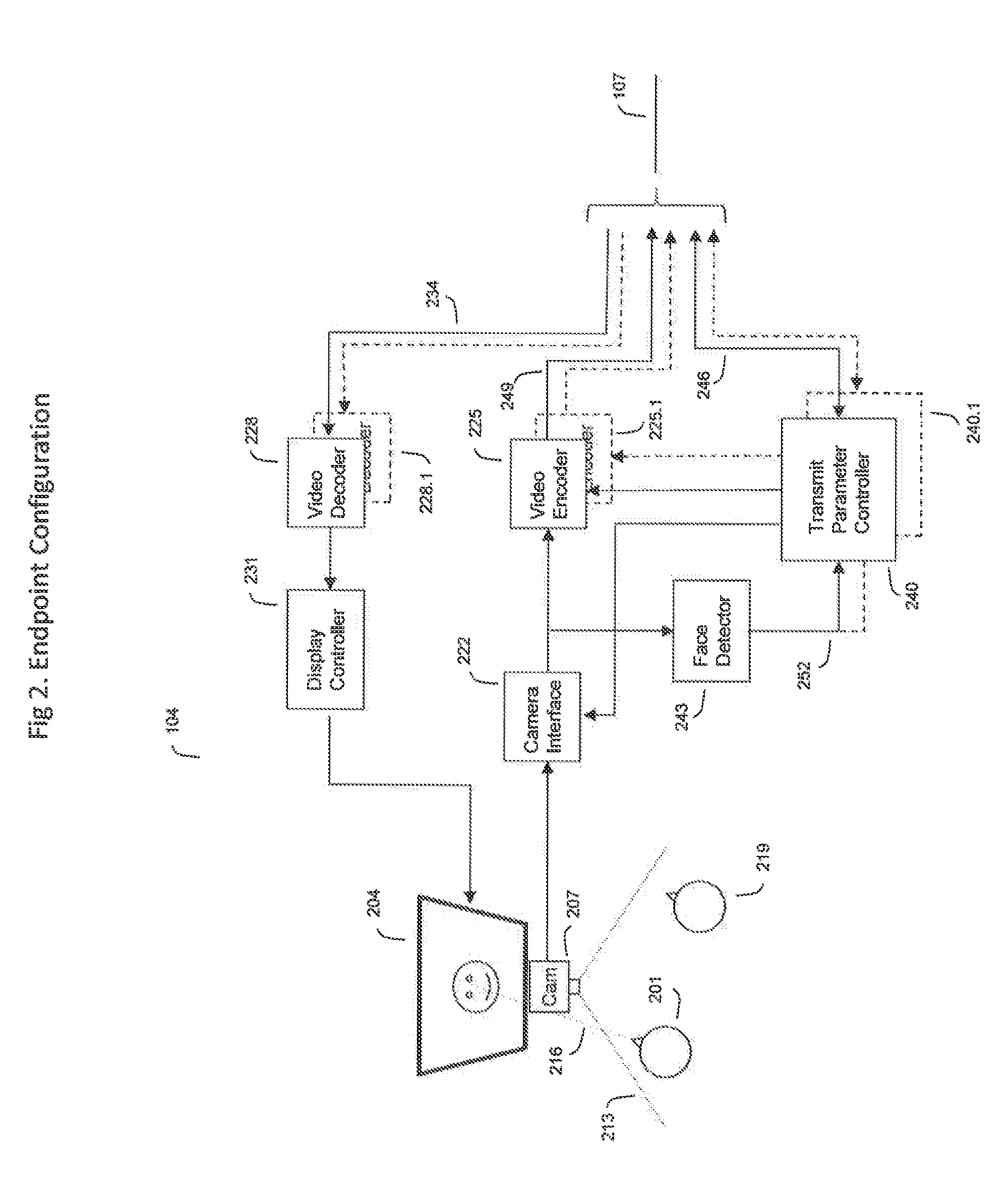
[0034]A typical video conference endpoint 104 is shown in block diagram form in FIG. 2.

[0035]A screen 204 and camera 207 are collocated. Preferably, as is typical in video conference for best eye contact of conferees, the camera and screen are horizontally centered and the camera sits just above or just below (illustrated case) the screen.

[0036]The camera has preferably a wide angle lens or, if it is adjustable, is set to a wide angle 213 so that most people 201 in the vicinity of the screen and interested in action at the remote location displayed on the screen will captured by the camera.

[0037]The video signal from the camera 207 via the Camera Interface 222 is distributed to both the Video Encoder (and transmitter) 225 and a Face / Eye Detector function 243.

[0038]The Camera Interface 222 and Video Encoder 225 are typical of those found in any video system except that certain parameters may be controlled by the transmit parameter controller 240, which receives inputs from the local ...


PUM


Abstract

Disclosed is a video conferencing endpoint comprising a camera interface for receiving local video from a local camera, a video encoder for encoding the local video from the camera interface for transmission to a remote endpoint over a communications channel, a feature detector for determining whether a feature is present in the local video received from the local camera, and a transmit parameter controller operative to control the video encoder to change at least one transmit parameter in response to at least one of: the presence or absence of the feature in the received local video, and a signal received from a remote endpoint indicating the presence or absence of a feature in the video acquired at the remote endpoint.

Description

CROSS REFERENCE TO RELATED APPLICATION[0001]This application claims the benefit under 35 USC 119(e) of U.S. Provisional Application Nos. 62 / 021,081 filed Jul. 4, 2014 and 62 / 033,895 filed Aug. 6, 2014, the contents of which are incorporated by reference herein.FIELD OF THE INVENTION[0002]This invention relates to the field of video conferencing, and in particular to a method of controlling bandwidth in an always on video conferencing system.BACKGROUND OF THE INVENTION[0003]With the increased availability of low cost hardware capable of providing a video conference or telepresence endpoint, users are extending the application of video beyond its original purpose of a formal meeting to a conceptual “digital water cooler” or “virtual (bi-directional) window”. This means that the video connections and devices are left in an “always-on” mode so that when a person looks at a display screen it is already showing activity at a distant location.[0004]The context of the present invention is t...

Claims


Application Information

Patent Timeline
IPC IPC(8): H04N19/87H04N7/15
CPCH04N7/15H04N19/87H04N7/147
Inventor HOSSEINI, MOJTABA
Owner MAGOR COMM CORP
Learn More