Wireless terminal, wireless communication system, handover method and recording medium

a wireless communication system and terminal technology, applied in the field of wireless communication systems, wireless communication systems, handover methods and recording media, can solve the problems of deteriorating affecting the quality of received signals, so as to improve the uplink throughput and reduce power consumption

Active Publication Date: 2016-01-07
NEC CORP
View PDF7 Cites 4 Cited by
  • Summary
  • Abstract
  • Description
  • Claims
  • Application Information

AI Technical Summary

Benefits of technology

[0016]According to the present invention, in a wireless communication system including a wireless terminal communicating with both the current serving base station and its neighboring base station which are capable of performing multi-base-station cooperative transmission, it becomes possible to achieve at least either improvement in the uplink throughput or reduction in power consumption at the wireless terminal.

Problems solved by technology

In such an area where two or more cells overlap, interference may occur between radio waves from respective ones of the corresponding base stations.
If such radio wave interference occurs, it results in deterioration in the quality of received signals, for example, SINR (Signal to Interference and Noise power Ratio).
Therefore, a wireless communication system including a plurality of base stations has a problem in that the communication throughput may be reduced when a wireless terminal is present near a cell edge.

Method used


Image

  • Wireless terminal, wireless communication system, handover method and recording medium
  • Wireless terminal, wireless communication system, handover method and recording medium
  • Wireless terminal, wireless communication system, handover method and recording medium

Examples


first exemplary embodiment

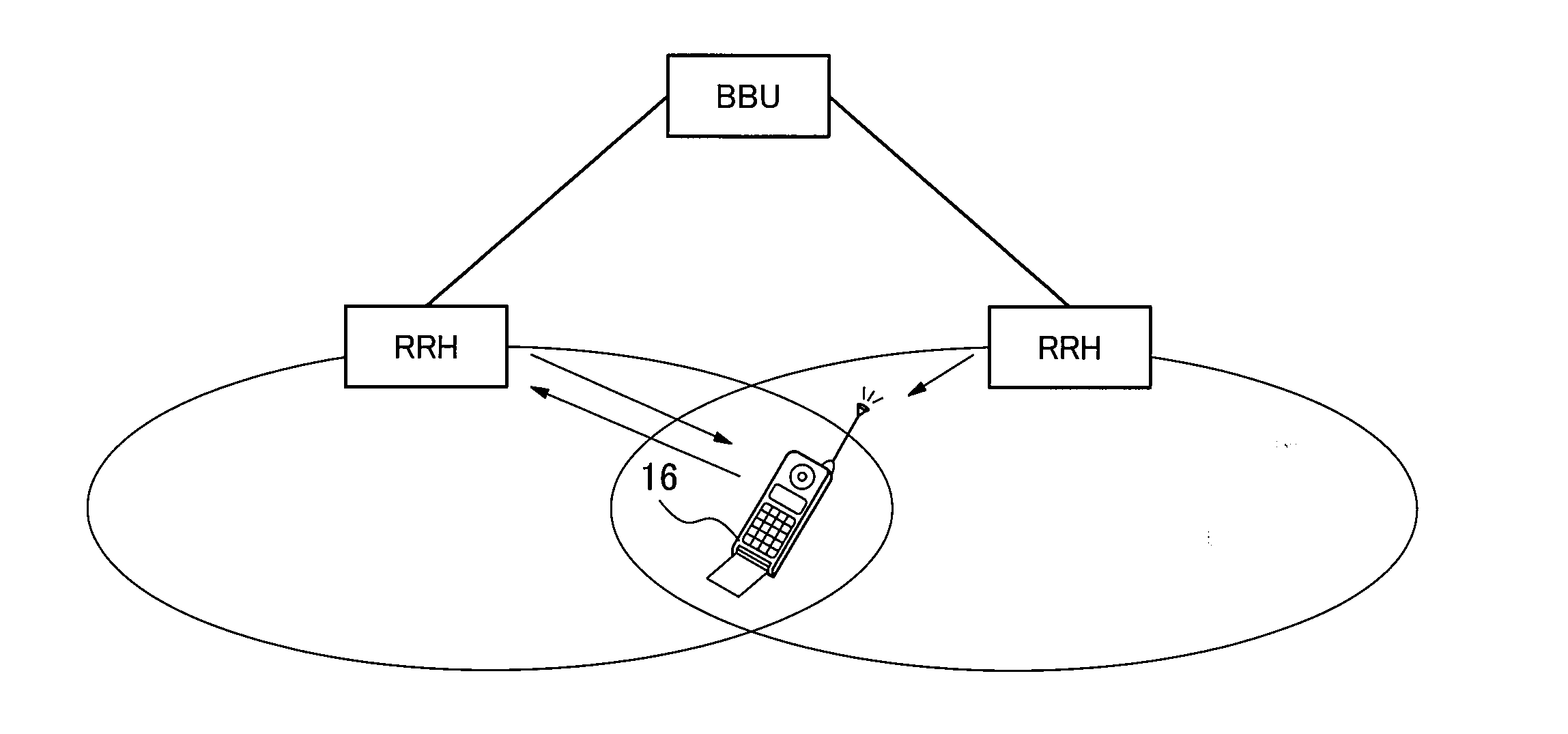
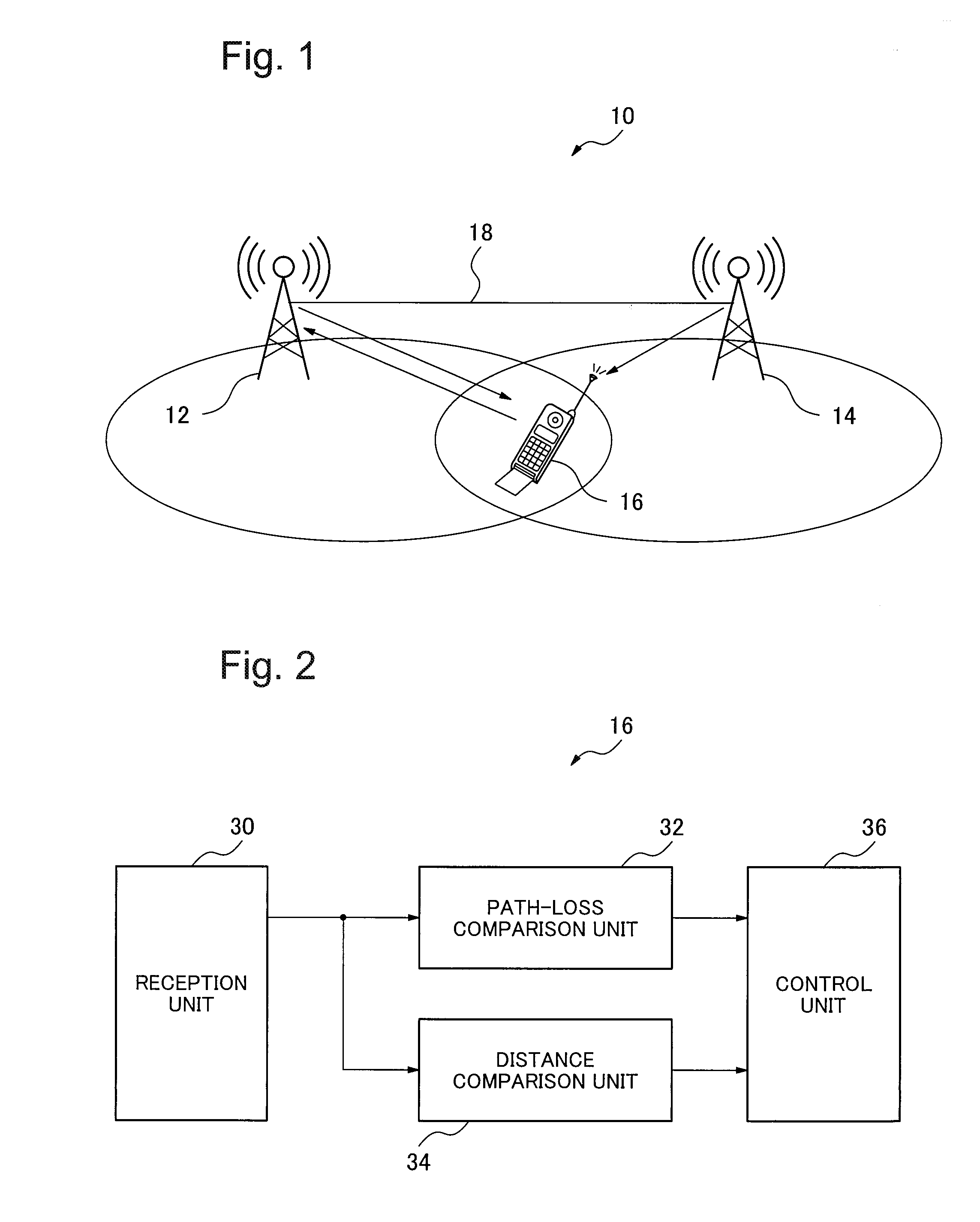
[0023]FIG. 1 is a system configuration diagram showing an example of a wireless communication system 10 according to a first exemplary embodiment of the present invention. The wireless communication system 10 includes a first base station 12, a second base station 14 and a wireless terminal 16. The wireless communication system is, for example, an LTE system.

[0024]The first base station 12 and the second base station 14 perform transmission of wireless signals in cooperation with each other, by the use of signaling through a wired transmission line 18. That is, in the wireless communication system 10, multi-base-station cooperative transmission (for example, CoMP) is performed.

[0025]In FIG. 1, the wireless terminal 16 is located in an area (a cell edge) where the cell of the first base station 12 overlaps with that of the second base station 14. In the present case, the wireless terminal 16 is currently served by the first base station 12. That is, in that situation, the first base ...

second exemplary embodiment

[0065]FIG. 5 is a block diagram showing an example of a configuration of a wireless terminal 50 according to a second exemplary embodiment of the present invention. The wireless terminal 50 comprises a CPU (Central Processing Unit) 52 and a memory 54.

[0066]The memory 54 stores a handover program 60. The CPU 52 executes the handover program 60. What can be mentioned as an example of the memory 54 is a non-transitory storage means such as, for example, a ROM (Read Only Memory), a hard disk, a removable medium or a removable disk.

[0067]FIG. 6 is a block diagram showing an example of a configuration of the handover program 60. The handover program 60 comprises a first program 62, a second program 64 and a third program 66.

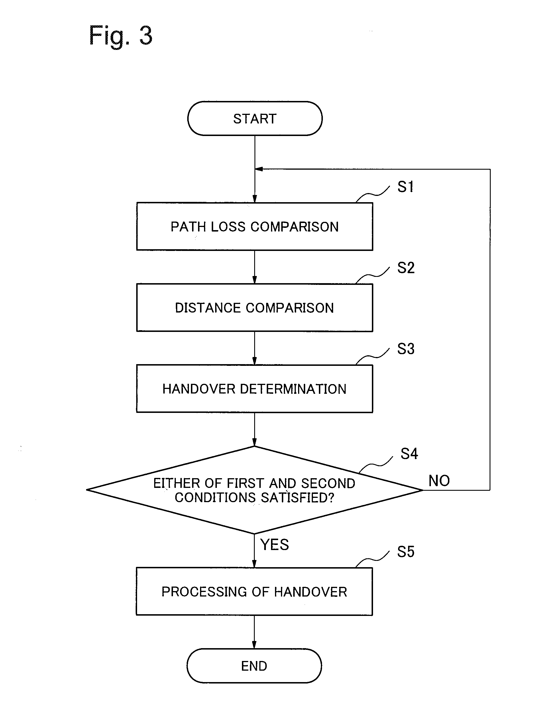
[0068]The first program 62 is a program for performing the process of the step Si in FIG. 3.

[0069]The second program 64 is a program for performing the process of the step S2 in FIG. 3.

[0070]The third program 66 is a program for performing the processes of the steps S3...


PUM


Abstract

A wireless communication system includes a wireless terminal and a neighboring base station capable of performing coordinated multi point transmission. The wireless terminal includes a path-loss comparison unit comparing a first path loss, including a path loss between the wireless terminal and the current serving base station, with a second path loss, including a path loss between the wireless terminal and the neighboring base station; a distance comparison unit comparing a first distance, including a distance between the wireless terminal and the current serving base station, with a second distance, including a distance between the wireless terminal and the neighboring base station; and a control unit performing handover from the current serving base station to the neighboring base station, if at least either the second path loss is smaller than the first path loss or the second distance is shorter than the first distance.

Description

TECHNICAL FIELD[0001]The present invention relates to a wireless terminal, a wireless communication system, a handover method and a recording medium, in which handover between a plurality of base stations is performed.BACKGROUND ART [0002]In a general wireless communication system, at an edge part of a cell of a certain base station, the cell overlaps with that of a neighboring base station. In such an area where two or more cells overlap, interference may occur between radio waves from respective ones of the corresponding base stations. If such radio wave interference occurs, it results in deterioration in the quality of received signals, for example, SINR (Signal to Interference and Noise power Ratio). Accordingly, the certain base station comes to have no choice but to change the modulation method from that for high speed communication to that for medium to low speed communication. Therefore, a wireless communication system including a plurality of base stations has a problem in ...

Claims


Application Information

Patent Timeline
Patent Type & Authority Applications(United States)
IPC IPC(8): H04W36/00H04B7/02H04W36/30H04W36/32
CPCH04W36/0094H04B7/024H04W36/32H04W36/30H04W36/0069Y02D30/70
Inventor ASADA, SHIRO
Owner NEC CORP
Why Eureka
Try Eureka