Structure

Active Publication Date: 2016-01-14
AIRBUS OPERATIONS LTD
View PDF13 Cites 7 Cited by
  • Summary
  • Abstract
  • Description
  • Claims
  • Application Information

AI Technical Summary

Benefits of technology

[0009]Regardless of the method of formation of the rib foot, the layers which run around the corners provide efficient load transfer between the adjacent parts of the rib foot which are connected by the corner.
[00

Problems solved by technology

Assembly of such a wing box can be very time-consuming and complicated due to the need to manufacture, drill, shim and then bolt many components t

Method used


Image

  • Structure
  • Structure
  • Structure

Examples


Embodiment Construction

)

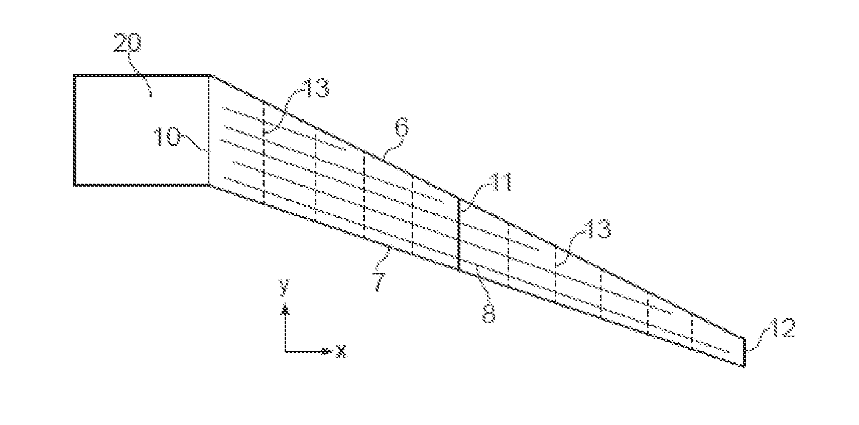
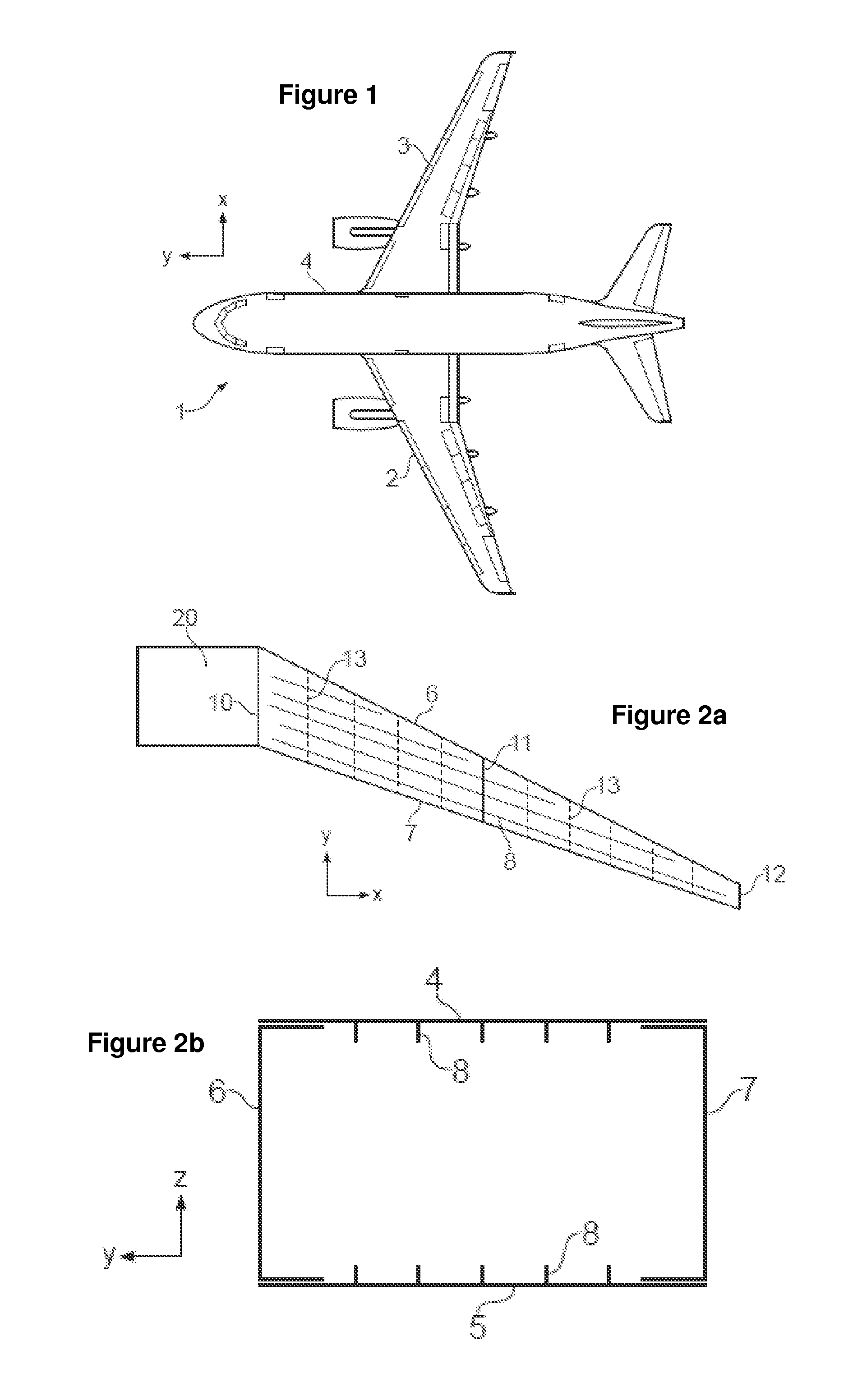
[0055]FIG. 1 shows an aircraft 1 with port and starboard wings 2, 3. Each wing has a cantilevered structure with a length extending in a spanwise direction from a root to a tip, the root being joined to an aircraft fuselage 4. The wings 2, 3 are similar in construction so only the starboard wing 3 will be described in detail with reference to FIGS. 2a and 2b.

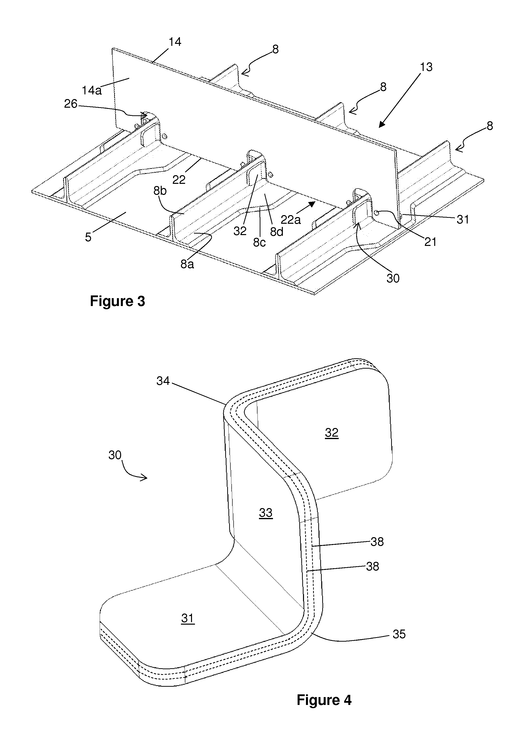
[0056]The main structural element of the wing is a wing box formed by upper and lower covers 4, 5 and front and rear spars 6, 7 as shown in FIGS. 2a and 2b. The covers 4, 5 and spars 6, 7 are each Carbon Fibre Reinforced Polymer (CFRP) laminate components. Each cover is a panel with an aerodynamic surface (the upper surface of the upper cover 4 and the lower surface of the lower cover 5) over which air flows during flight of the aircraft. Each cover also has an inner surface carrying a series of stringers 8 extending in the spanwise direction. Each cover carries a large number of stringers 8, only five of which are shown in FI...


PUM

PropertyMeasurementUnit
Aerodynamicaaaaaaaaaa

Abstract

A structure having a panel, a stringer, and a rib is disclosed. The stringer includes a stringer flange that is joined to the panel and a stringer web that extends away from the stringer flange. The rib includes a rib web that has first and second faces and a rib foot that has a first rib foot flange that is joined to the stringer web, a second rib foot flange that is joined to the panel and a rib foot web that is joined to the first face of the rib web. The first rib foot flange is connected to the rib foot web by a first corner that includes at least one layer which runs continuously from the first rib foot flange into the rib foot web via the first corner. The second rib foot flange is connected to the rib foot web by a second corner that includes at least one layer which runs continuously from the second rib foot flange into the rib foot web via the second corner.

Description

FIELD OF THE INVENTION[0001]The present invention relates to a structure. More particularly, although not exclusively, the present invention relates to an aircraft structure, for example a wing, horizontal stabiliser or vertical stabiliser.BACKGROUND OF THE INVENTION[0002]Traditional aircraft wings have a wing box formed by upper and lower aerodynamic covers, front and rear spars, and a series of transverse ribs spaced apart along the span-wise length of the wing box. Each rib is bolted to the upper and lower covers and reacts fuel pressure loads between them.[0003]Assembly of such a wing box can be very time-consuming and complicated due to the need to manufacture, drill, shim and then bolt many components together. A traditional wing box is also very heavy and does not always make the most efficient use of modern aerospace materials such as composites.[0004]It is desirable to design an aircraft wing box or similar which has a reduced part count, simplified manufacturing process an...

Claims


Application Information

Patent Timeline
IPC IPC(8): B64C3/18B29C53/04B64C3/26B64C5/00
CPCB64C3/18B64C5/00B29L2031/001B29C53/04B64C3/26B64C1/06B64C1/064B64C1/065B64C1/12B64C3/182B64C3/187B29C66/721B29D99/0014
Inventor MARKS, OLIVEREVANS, STEVEN
Owner AIRBUS OPERATIONS LTD
Why Eureka
Try Eureka