Electromechanical screw drive actuator

Active Publication Date: 2005-08-09
WARNER ELECTRIC
View PDF10 Cites 39 Cited by
  • Summary
  • Abstract
  • Description
  • Claims
  • Application Information

AI Technical Summary

Benefits of technology

[0015]This aspect of the invention transfers the actuator load directly through the screw shaft and into the attachment end fitting with an efficient ball bearing arrangement using the large single ball for compression load transfer and the plurality of smaller balls around the perimeter of the screw shaft for tension loads. This multi-ball arrangement around the circumference of the screw shaft also provides rotational bearing support of the shaft. This unique configuration is more efficient in load transfer using less parts, less horsepower loss, larger load capability in a similar unit size and results in a quieter design.
[0016]The result of this bearing arrangement is the ability to move loads with more efficiency. The efficiency is achieved because the IBBSEF allows the screw and nut assembly to have less frictional drag with both thrust and side loads applied. The higher efficiency is seen as lower current draw on the motor, and higher load capability versus a dimensionally and functionally similar competitive actuator.
[0017]In another aspect of the present invention, the extension rod driven by the drive screw rides on an acetyl bearing at the end of the drive screw. This bearing support is used in conjunction with a like acetyl extension rod bearing in the extension rod. This provides a solid extension rod bearing support providing larger side load capability of the actuator. Additionally, when used with the attachment end ball bearing configuration, this aspect provides a stable two-point bearing configuration for the screw shaft. This results in more efficiency, less side load drag, compensation for misalignment and greater column load capability.
[0018]Further, the acetyl extension rod bearing attached to the screw also serves two other purposes. It provides a solid means of end travel stop. The acetyl bearing provides the stop while also minimizing the tendency for lockup due to its low friction characteristics. Prior designs use needle bearings for this purpose. The

Problems solved by technology

However, this arrangement of the thrust bearing and thrust washers causes the axial load on the thrust shaft to be transferred radially to the gearbox housing structure.
As a result, stronger gearbox housings are required at a substantially increased cost.
As will be apparent to those skilled in the art, the application of the linear actuators in the rugged service industries identified above subjects the actuators to harsh, all weather environments.
Unfortunately, in current designs these foreign object exclusion requirements have resulted in several problems.
In extreme operating environments, this increased heat may cause binding between the end rod support bearing and the extension rod such that the efficiency of the extension and retraction of the linear actuator is decreased.
Further, the increased friction tends to further increase the heating of the bearing and extension rod, and may result in damage to the exterior surface of the extension rod with continued operation during such conditions.
Another problem relates to the fact that within the sealed extension rod there is a rolled screw end configuration with integral rod support that provides the internal support for the extension rod in coordination with the external end support bearing just discussed.
The pressure in each of these two cavities tends to in

Method used


Image

  • Electromechanical screw drive actuator
  • Electromechanical screw drive actuator
  • Electromechanical screw drive actuator

Examples


Embodiment Construction

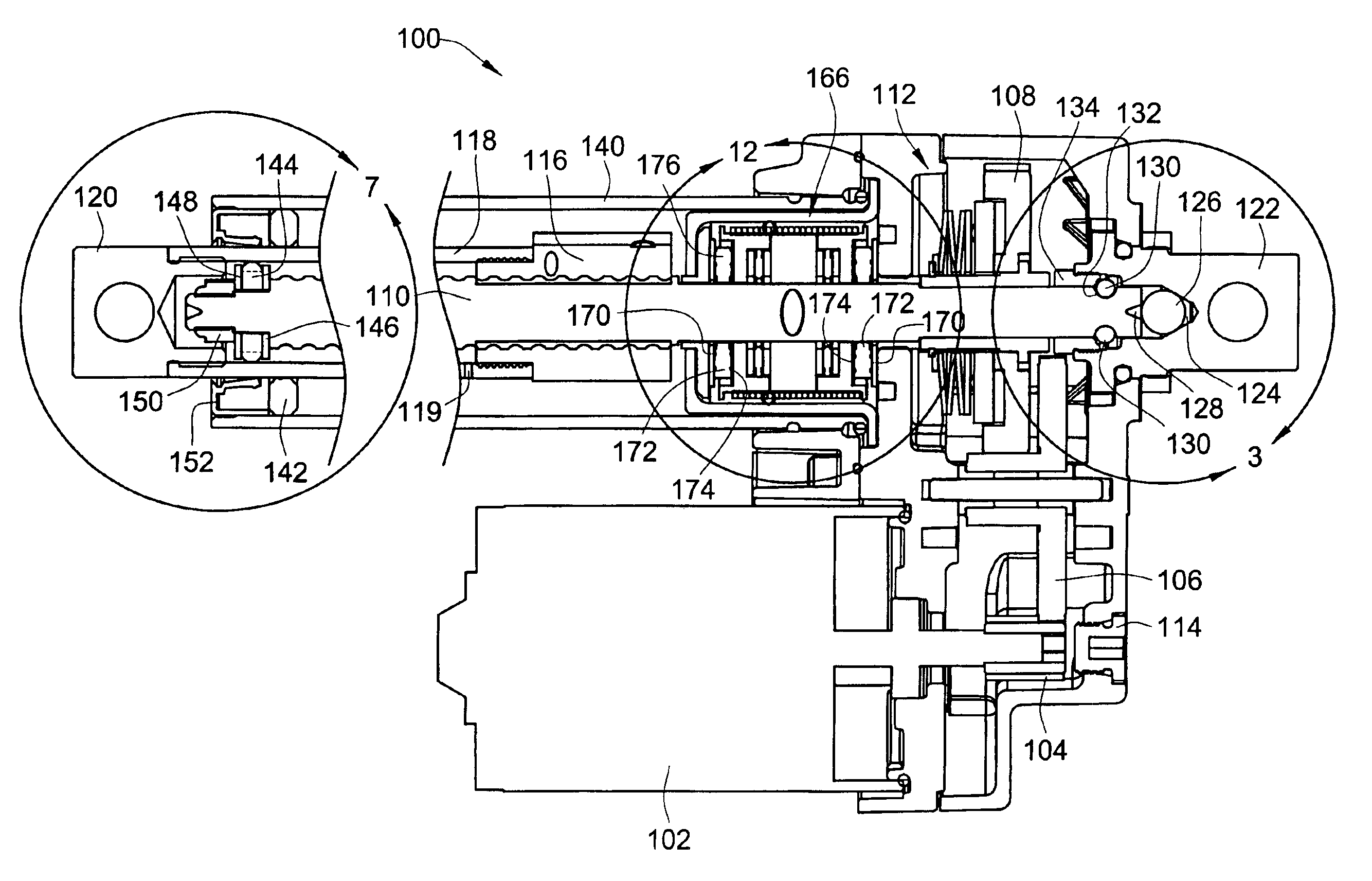
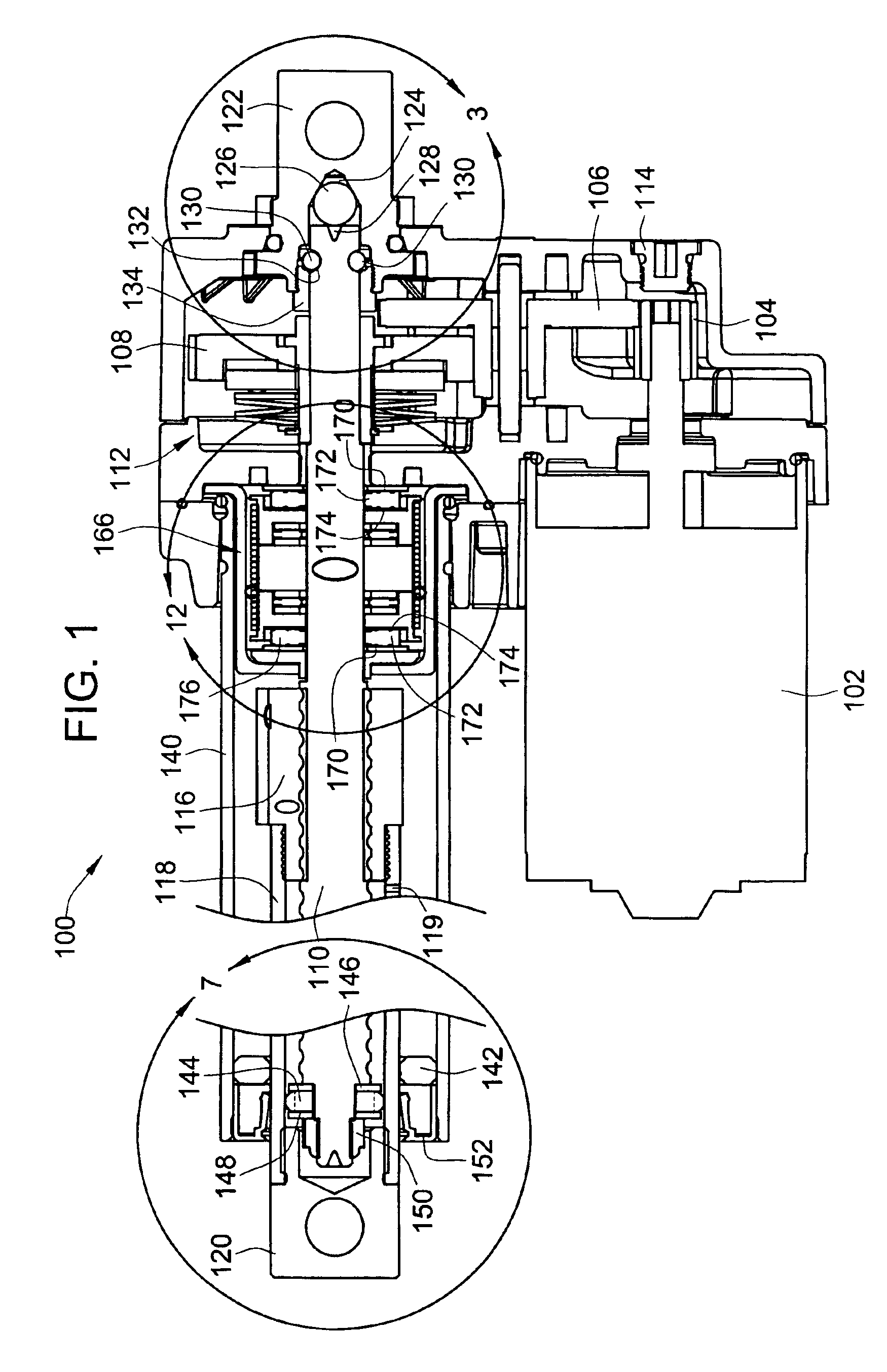
[0044]Turning now to the drawings, there is illustrated in FIG. 1 a simplified cross-sectional view of an embodiment of an electromechanical screw drive actuator 100 constructed in accordance with the teachings of the present invention. In this embodiment, an electric motor 102 is drivably coupled through an output gear train assembly, including output pinion gear 104, reducer gear 106 and drive gear 108, to a drive screw shaft 110. In the embodiment shown in FIG. 1, a clutch assembly 112 is used to provide the final drive coupling between the final drive gear 108 and the actual drive screw shaft 110 to protect the gear assembly and motor from transient mechanical shock loads that might otherwise damage the teeth of the gears. A manual override access point 114 is provided to allow manual control of the actuator 100 without requiring electric power to be supplied thereto. This manual override is particularly helpful during installation of the actuator 100. It should be noted, that w...


PUM


Abstract

An electromechanical linear actuator assembly having in-line axial load support of its screw drive shaft is provided. The bearing support structure provides a single in-line ball bearing accommodated within a hardened end fitting and a screw pivot recess in the axial screw drive shaft. For axial loading in an opposite direction, a number of smaller ball bearings are provided around the outer periphery of the screw shaft in a groove, and are retained within the hardened end fitting by a bearing retainer. End rod support bearings providing heat compensation and lubrication fluid transfer are also provided. A braking mechanism having increased life and more consistent load engagement is also provided. Further, integrated electronics may be provided for position sensing and power efficiency control.

Description

CROSS-REFERENCE TO RELATED PATENT APPLICATIONS[0001]This patent application claims the benefit of U.S. Provisional Patent Application No. 60 / 392,915, filed Jul. 1, 2002.FIELD OF THE INVENTION[0002]The present invention relates generally to screw drive actuators, and more particularly to a bearing and load distribution system for use in linear screw drive actuators.BACKGROUND OF THE INVENTION[0003]Linear actuators, such as are used in rugged service industries such as turf care, specialty vehicles, agriculture, service vehicles, construction vehicles, and material handling, typically use a motor (electric or hydraulic), a gear box of a specified ratio, and a screw and nut combination to extend and retract a load. To provide the strongest column load capability and load transfer, a steel screw assembly is designed to pass through an aluminum or zinc die cast gear box, and be secured at a hardened steel end fitting mounting bracket.[0004]In such a screw type linear actuator, the screw ...

Claims


Application Information

Patent Timeline
IPC IPC(8): F16H25/20H02K7/06
CPCF16H25/20H02K7/06F16H25/2204Y10T74/18576F16H2025/2463F16H2025/2081
Inventor SCHREIER, DENNIS MICHAEL
Owner WARNER ELECTRIC
Why Eureka
Try Eureka