Water heater

a water heater and water tank technology, applied in water heaters, indirect heat exchangers, lighting and heating apparatus, etc., can solve the problems of affecting the operation of water heaters

Active Publication Date: 2016-01-14
NORITZ CORP
View PDF4 Cites 12 Cited by
  • Summary
  • Abstract
  • Description
  • Claims
  • Application Information

AI Technical Summary

Benefits of technology

[0011]The present invention has been made in light of the above-described problems. An object of the present invention is to provide a water heater of a latent heat recovery type that: includes a drainage water discharge path having a water-sealing mechanism; and prevents occurrence of problems that combustion gas flows into the building and drainage water is difficult to be discharged from the secondary heat exchanger even for a time period until the drainage water discharge path is water-sealed.

Problems solved by technology

This may cause a problem that combustion gas that should originally be emitted to the outside of the building through an exhaust pipe (a B vent) is emitted through the drainage water discharge path to the inside of the building in which a water heater is arranged.
Consequently, it may become difficult to cause the drainage water to be discharged from the secondary heat exchanger.
However, even in the case of the water heater provided with a drainage water discharge path having a water-sealing mechanism, when performing a trial operation of a new water heater, or when resuming an operation of a water heater that has not been used for a long period of time or resuming an operation of a water heater or the like from which drainage water is removed for maintenance or freeze proofing, there occur problems that combustion gas in the water heater of a latent heat recovery type using a forced exhaust system described above flows into the building and the drainage water is difficult to be discharged from the secondary heat exchanger in the water heater of a latent heat recovery type using an exhaust suction system, for a time period from start of the operation until the drainage water discharge path is water-sealed.

Method used


Image

  • Water heater
  • Water heater
  • Water heater

Examples


first embodiment

[0032]The configuration of a water heater in the first embodiment of the present invention will be hereinafter described with reference to FIGS. 1, 2, and 4 to 10.

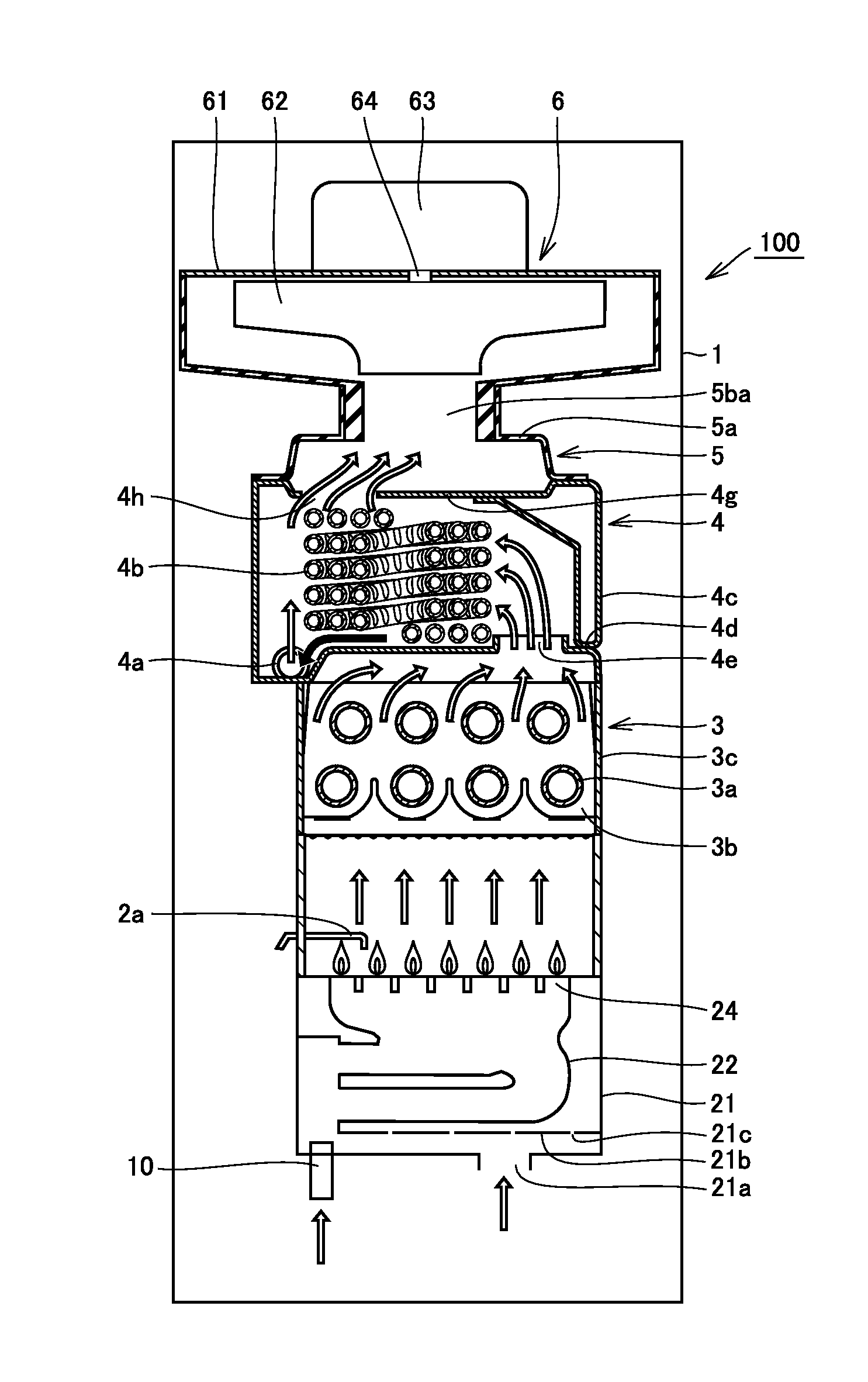
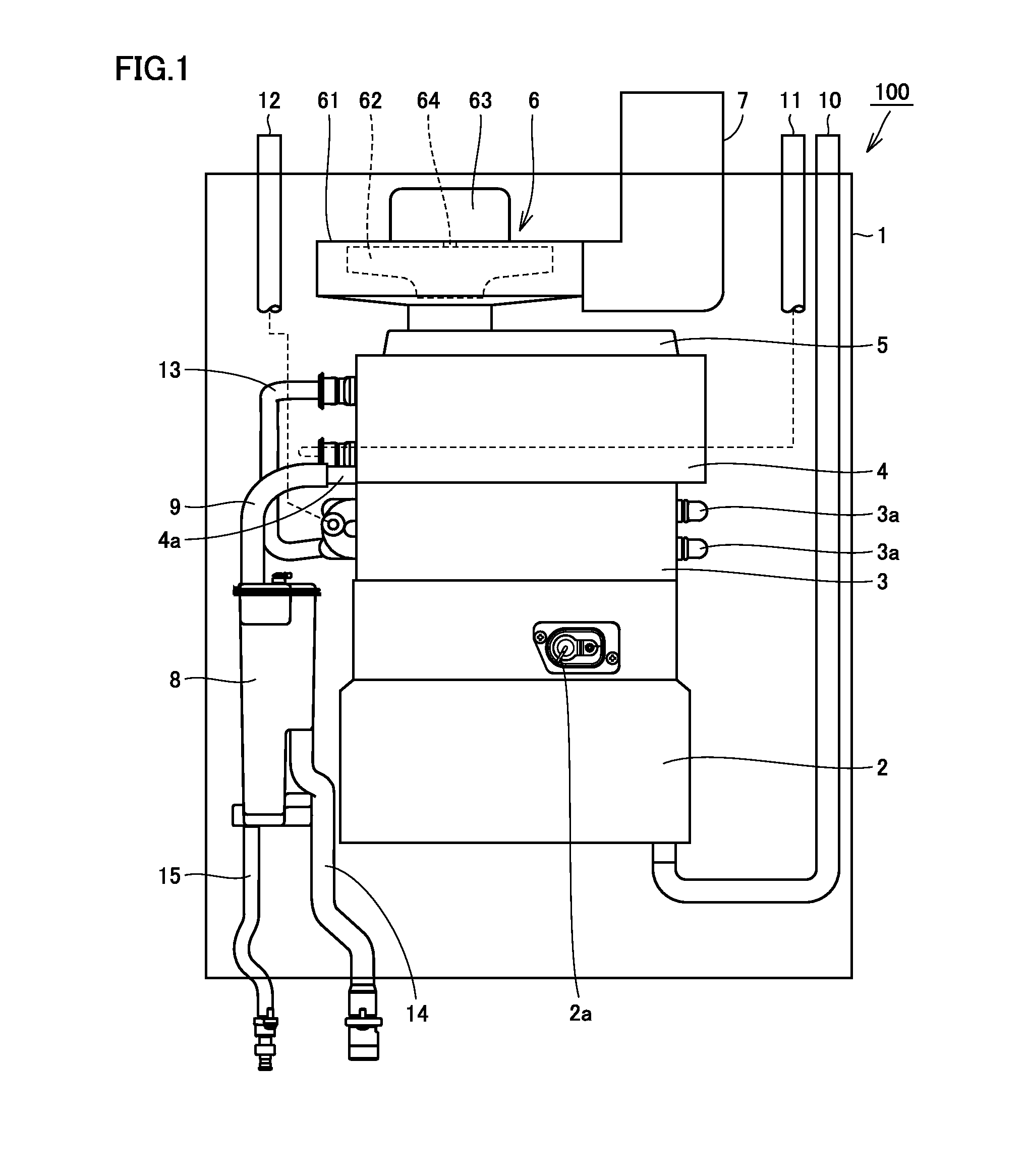
[0033]Referring mainly to FIGS. 1 and 2, a water heater 100 of the present embodiment serves as a water heater of a latent heat recovery type using an exhaust suction and combustion system. This water heater 100 mainly includes a housing 1, a burner 2, a primary heat exchanger 3, a secondary heat exchanger 4, an exhaust box 5, a fan 6, an exhaust tube (a flexible exhaust tube) 7, a drainage water tank 8, and pipes 9 to 15. In addition, since water heater 100 of the present embodiment is of an exhaust suction and combustion type, burner 2, primary heat exchanger 3, secondary heat exchanger 4, and fan 6 are arranged in this order from upstream to downstream in the flow of combustion gas.

[0034](Burner)

[0035]Referring mainly to FIGS. 1 and 2, burner 2 serves to produce combustion gas by burning fuel gas, and includes a combust...

second embodiment

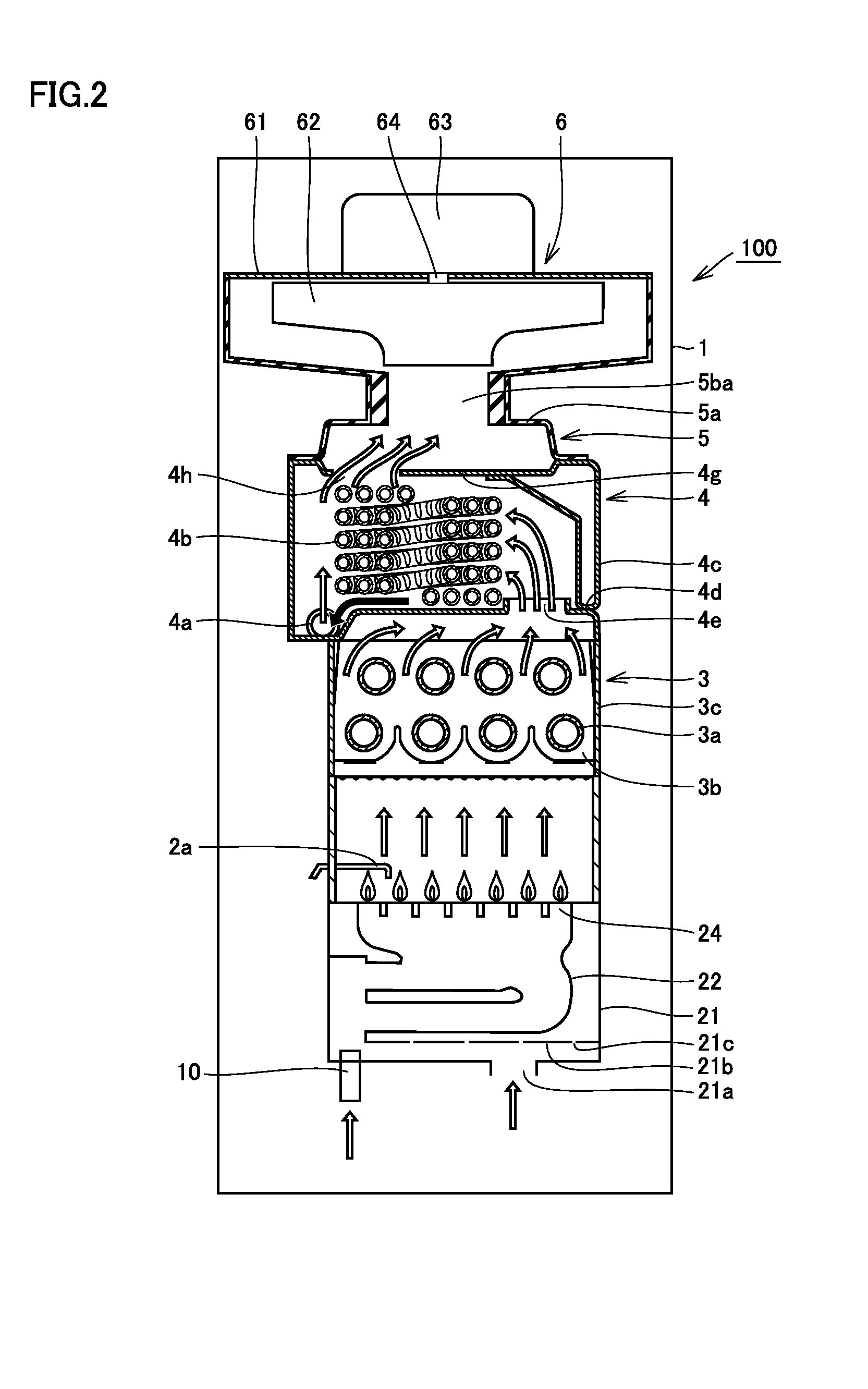
[0101]The configuration of the water heater in the second embodiment of the present invention will be hereinafter described with reference to FIGS. 3 to 10. The water heater of the present embodiment is a water heater of a forced exhaust type in which fan 6 is configured to be arranged upstream of the heat exchanger in the flow direction of combustion gas to force air into the burner, and also configured to force air into the water heater thereby emitting combustion gas, which have passed through the heat exchanger, to the outside of the water heater. Thus, fan 6, burner 2, primary heat exchanger 3, and secondary heat exchanger 4 are arranged in this order from upstream to downstream in the flow of combustion gas. The present embodiment is different in the above-described points from the first embodiment, but basically similar in other points to the first embodiment. Accordingly, the same explanation as that of the first embodiment will not be repeated.

[0102]In water heater 100 of t...


PUM


Abstract

A water heater includes: a burner; a heat exchanger; a fan for supplying air to the burner and emitting combustion gas having passed through the heat exchanger to outside of the water heater; and a drainage water discharge path connected to the heat exchanger. The drainage water discharge path has a water-sealing structure that is water-sealed by drainage water. The water heater further includes a control unit: having a water-seal determination unit giving permission that the water heater can operate in a normal mode based on a condition that the drainage water discharge path has been water-sealed; and issuing an instruction to cause the burner to intermittently operate for a time period until the water-seal determination unit gives the permission.

Description

BACKGROUND OF THE INVENTION[0001]1. Field of the Invention[0002]The present invention relates to a water heater and particularly to a water heater of a latent heat recovery type capable of heating water by recovering latent heat of combustion gas.[0003]2. Description of the Background Art[0004]In addition to a primary heat exchanger for mainly recovering sensible heat of combustion gas, a water heater of a latent heat recovery type includes a secondary heat exchanger for mainly recovering latent heat. This water heater of a latent heat recovery type can obtain condensation heat (latent heat) by condensing water vapor contained in combustion gas, so that it can achieve relatively high thermal conversion efficiency.[0005]According to such a water heater of a latent heat recovery type, condensation of water vapor occurs in combustion gas within the secondary heat exchanger, thereby producing drainage water (dew condensation water). At this time, combustion gas contains nitrogen oxides ...

Claims


Application Information

Patent Timeline
Patent Type & Authority Applications(United States)
IPC IPC(8): F24H9/20F24H1/14F24H8/00
CPCF24H9/2042F24H8/006F24H1/145F24H8/00F24H9/1836Y02B30/00F24H15/235F24H15/36F24H15/238F24H15/215F24H15/31F24H15/219F24H15/35F24H15/112
Inventor KIMURA, SAKIKOOOHIGASHI, TAKESHI
Owner NORITZ CORP
Why Eureka
Try Eureka