Angle sensor, a bearing unit, electrical motor, a control system and error-check system

a control system and angle sensor technology, applied in the field of angle sensors, can solve problems such as difficult use of angle sensors, and achieve the effects of simple linear relationship, increased error in the determination of electrical angle signals, and high accuracy

Active Publication Date: 2016-01-14
AB SKF
View PDF3 Cites 8 Cited by
  • Summary
  • Abstract
  • Description
  • Claims
  • Application Information

AI Technical Summary

Benefits of technology

[0009]The use of the first plurality of first grating elements and the second plurality of second grating elements in which the first plurality and the second plurality are co-prime numbers enables the use of a simple linear relationship for calculating the absolute angle signal, while the difference between the first plurality and the second plurality is larger than 1. In the known angle sensors the difference in number of magnetic poles between the two magnetic encoders is equal to 1. This is convenient as it enables to determine the absolute angle signal simply from a difference signal resulting from subtracting a first signal from the first magnetic encoder from a second signal from the second magnetic encoder. Due to the difference between the number of magnetic poles between the two magnetic encoders in the known configuration the determined difference signal repeats itself only once every 360 degrees of the rotation angle, thus enabling the determination of the absolute angle signal. In the angle sensor according to the invention the first plurality and the second plurality are co-prime numbers. The inventors have found that due to this co-prime relationship between the first plurality and the second plurality, the first plurality of the first grating elements and the second plurality of the second grating elements comply with the Bezout identity enabling a simple linear relationship to calculate the absolute angle signal (see detailed description for further details). As a result, the difference between the first plurality of first grating elements and the second plurality of second grating elements may easily be larger than 1 to still be able to determine the absolute angle signal from the angle sensor. A further benefit, when allowing the difference between the first plurality and the second plurality to be larger than 1, is that this same angle sensor may also be used to calculate, in addition to the absolute angle signal, an electrical angle signal of an electrical motor at relatively high accuracy.
[0010]So in an embodiment of the angle sensor according to the invention the angle sensor is further configured for determining both the absolute angle signal and an electrical angle signal of an electrical motor using the first grating ring and the second grating ring. In the angle sensor according to this embodiment, a difference between the first plurality (n1) and the second plurality (n2) being equal to a number of magnetic pole pairs of the electrical motor, and wherein the calculator is configured for calculating the electrical angle signal by calculating the difference between the first signal and the second signal. In the known angle sensors in which the difference in number of magnetic poles between the two magnetic encoders is equal to 1, the determination of both the absolute angle signal and the electrical angle signal using a single pair of magnetic encoders is not accurate enough. To calculate the electrical rotation angle in this known configuration the absolute angle signal has to be multiplied with the number of magnetic pole pairs present in the electrical motor. This multiplication of the absolute angle signal significantly increases the error in the determined electrical angle signal, especially when the number of magnetic pole pairs in the electrical motor is relatively high. As a result, the known angle sensor requires a further magnetic encoder to also determine the electrical rotational angle signal accurately. In the angle sensor according to the present invention, the first plurality and second plurality are co-prime numbers in which the difference between the first plurality and the second plurality is larger than 1. This difference between the first plurality and the second plurality is further also equal to the number of magnetic pole pairs present in the electrical motor. As a result, the electrical angle signal may be calculated by calculating the difference between the first signal and the second signal. Especially in an embodiment in which the number of magnetic pole pairs of the electrical motor is relatively high, the determination according to the current invention results in a significant improvement in the accuracy and in avoiding the requirement of a further magnetic encoder.
[0012]In an embodiment of the angle sensor, the first grating ring is a magnetic encoder having the first plurality of grating elements being the first plurality of magnetic poles, and / or the second grating ring is a magnetic encoder having the second plurality of grating elements being the second plurality of magnetic poles. A benefit of using magnetic encoders is that it enables a relatively robust angle sensor which may also be used in, for example, a greasy environment such as with bearings.
[0048]In an embodiment of the error-check system, the error-check system further comprises a low-pass filter for eliminating high-frequency noise from the absolute angle signal.

Problems solved by technology

However, in a bearing environment with grease obscuring the disc, these types of angle sensors are difficult to use.

Method used


Image

  • Angle sensor, a bearing unit, electrical motor, a control system and error-check system
  • Angle sensor, a bearing unit, electrical motor, a control system and error-check system
  • Angle sensor, a bearing unit, electrical motor, a control system and error-check system

Examples


example

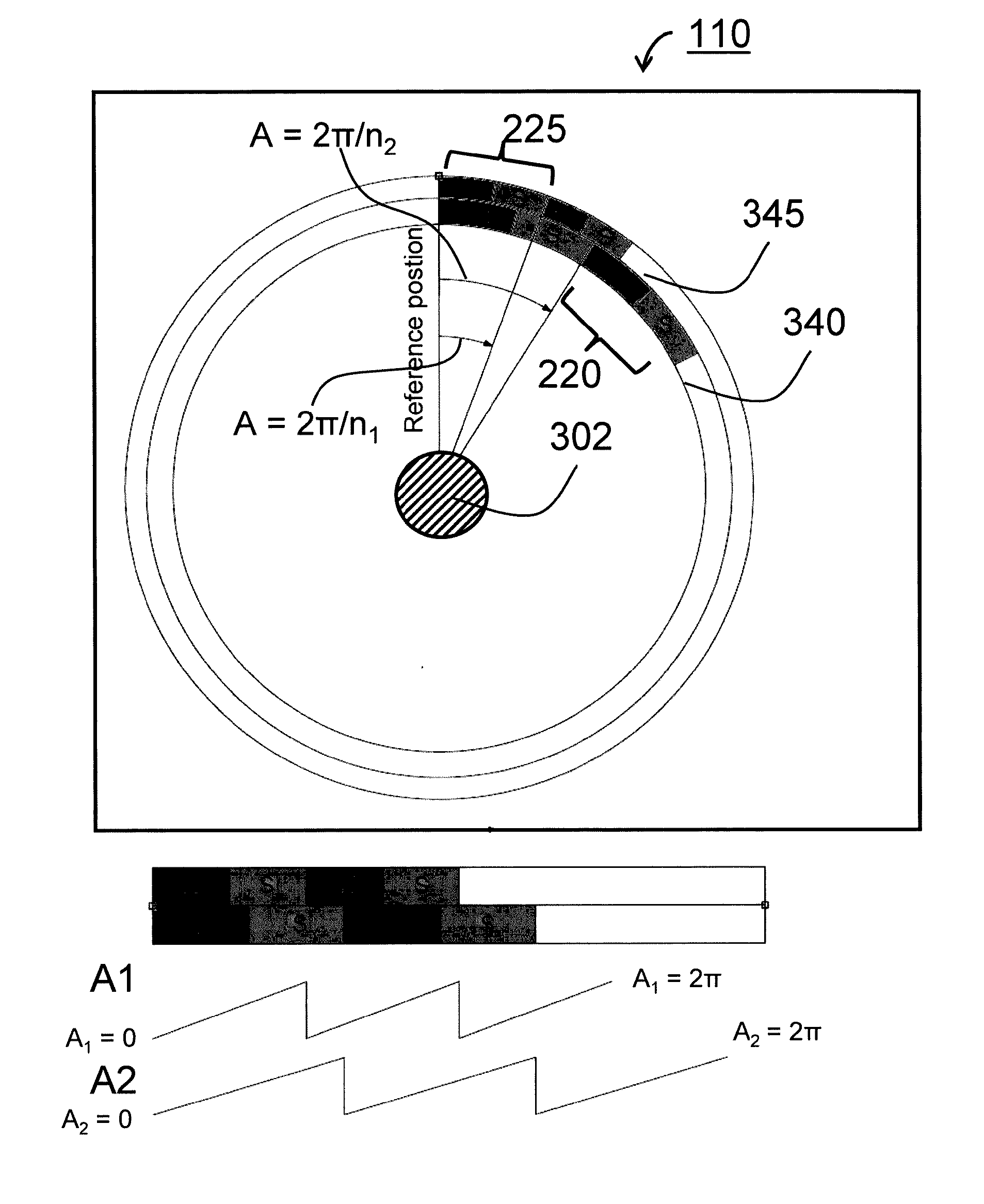
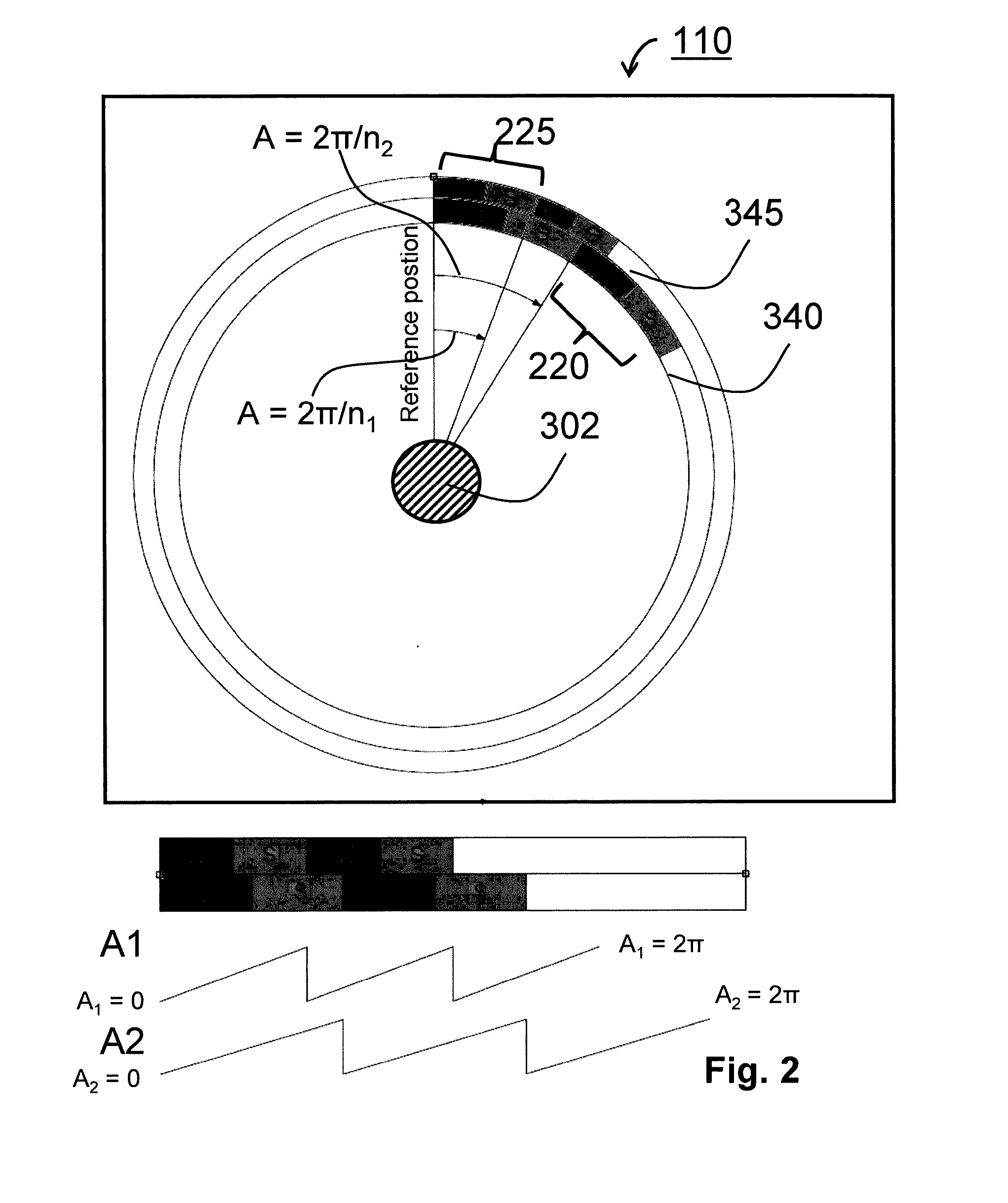
[0085]Assume n1=143 and n2=119. The Bezout numbers are then 5 and −6. (143×5+119×(−6)=1)

[0086]After measuring the first signal A1 (angle of the outer ring), and the second signal A2 (angle of the inner ring), the absolute angle signal AA of the shaft is simply given as 5A1−6A2.

[0087]The second embodiment of this invention is about making the absolute angle signal AA more accurate and preserving the accuracy of the electrical angle signal EA. In a design example, n1=144 and n2=120. Electrical angle signal EA, which is required to have a frequency 24 times the mechanical frequency is immediately obtained by subtracting A2 from A1.

EA=A1−A2

[0088]What is noteworthy about this design is that exactly 6 revolutions of A1 fit in each revolution of the electrical angle signal EA (144 / 24=6). This allows for a refinement procedure which increases the accuracy of EA by a factor of 6√{square root over (2)}. Details of this refinement procedure can be found with respect to FIGS. 6a to 6c. To expl...


PUM


Abstract

An angle sensor is provided for determining an absolute angle signal of a first part rotated with respect to a second part. The angle sensor comprises a first grating ring for generating a first signal representative of a relative position of a first sensor along a corresponding ring segment of the first grating ring. The angle sensor further comprises a second grating ring for generating a second signal representative of a relative position of a second sensor along the corresponding ring segment of the second grating ring. The first plurality and the second plurality are co-prime numbers and a difference between the first plurality and the second plurality being larger than 1. The angle sensor also comprises a calculator configured for calculating the absolute angle signal using a first linear combination of the first signal and the second signal.

Description

CROSS REFERENCE TO RELATED APPLICATIONS[0001]This is a United States National Stage Application claiming the benefit of International Application Number PCT / EP2013 / 053828 filed on 26 Feb. 2013 (26.02.2013), which is incorporated herein by reference in its entirety.FIELD OF THE INVENTION[0002]The present invention relates to an angle sensor for determining an absolute angle signal of a first part rotated with respect to a second part. The invention further relates to a bearing unit, an electrical motor, a control system for the electrical motor and an error-check system comprising the angle sensor. The invention also defines a method of determining the absolute angle signal and a computer program product.BACKGROUND OF THE INVENTION[0003]Angle sensors, also called rotary encoders or shaft encoders convert an angular position or motion of a shaft or axle to an analog or digital code. Known angle sensors of the mechanical type may use concentric rings with openings. At each angular posi...

Claims


Application Information

Patent Timeline
Patent Type & Authority Applications(United States)
IPC IPC(8): G01D5/244G01D5/245G01D5/36
CPCG01D5/2454G01D5/36G01D5/24428G01D5/245
Inventor ANGELIS, GEORGOYURTSEVEN, EVREN
Owner AB SKF
Why Eureka
Try Eureka