Method and device for determining a torque of an electrical machine

Inactive Publication Date: 2005-06-21
SEG AUTOMOTIVE GERMANY GMBH
View PDF1 Cites 5 Cited by
  • Summary
  • Abstract
  • Description
  • Claims
  • Application Information

AI Technical Summary

Benefits of technology

[0004]A prerequisite for determining the torque of an electrical machine is that the current generator or machine efficiency be known. Mathematically formulated relationships between the instantaneous electrical power of the generator and the generator rpm with the generator efficiency are quite complicated, and the relationship among these three variables is therefore advantageously stored in memory in a performance graph. The respective current efficiency is taken from there by a control unit, as a function of the generator power and generator rpm. Such a performance graph is ascertained beforehand for this purpose and stored in a memory medium. Storing the efficiency as a function of a performance graph is advantageous because in this way, the current efficiency is ascertained especially fast. The rpm of a drive shaft of a generator, typically a crankshaft, is known in modern engine control systems. To ascertain an rpm of the generator without additional expense for equipment, such as an rpm sensor, a simple calculation is possible, with the aid of a known gear ratio between a drive shaft of the generator and the generator shaft.
[0006]Alternatively, it is possible to determine the generator power as a function of the exciter current of the exciter coil and of the rpm of the generator. This can in turn be done relatively simply by taking the power output by the generator from a performance graph as a function of the exciter current and the generator rpm. The otherwise complicated relationship among the generator power, exciter current and rpm is simplified as a result, since the performance graph is obtained on the basis of prior measurement of generators.
[0007]The generator rpm can also be obtained by evaluating the frequency of the output voltage, for instance. Another possibility is to use an rpm sensor. Such a sensor, like ascertaining the generator rpm by way of the frequency of the output voltage, would have the advantage that the generator rpm is independent of slippage between the rpm of the drive shaft and the generator shaft. The rpm value ascertained by these last-named method steps is therefore more accurate.

Problems solved by technology

Because of the high efficient current intensity that a modern generator furnishes, relatively expensive current measuring instruments are required.

Method used


Image

  • Method and device for determining a torque of an electrical machine
  • Method and device for determining a torque of an electrical machine
  • Method and device for determining a torque of an electrical machine

Examples


Embodiment Construction

[0014]Components that are identical or function the same are identified by the same reference numerals.

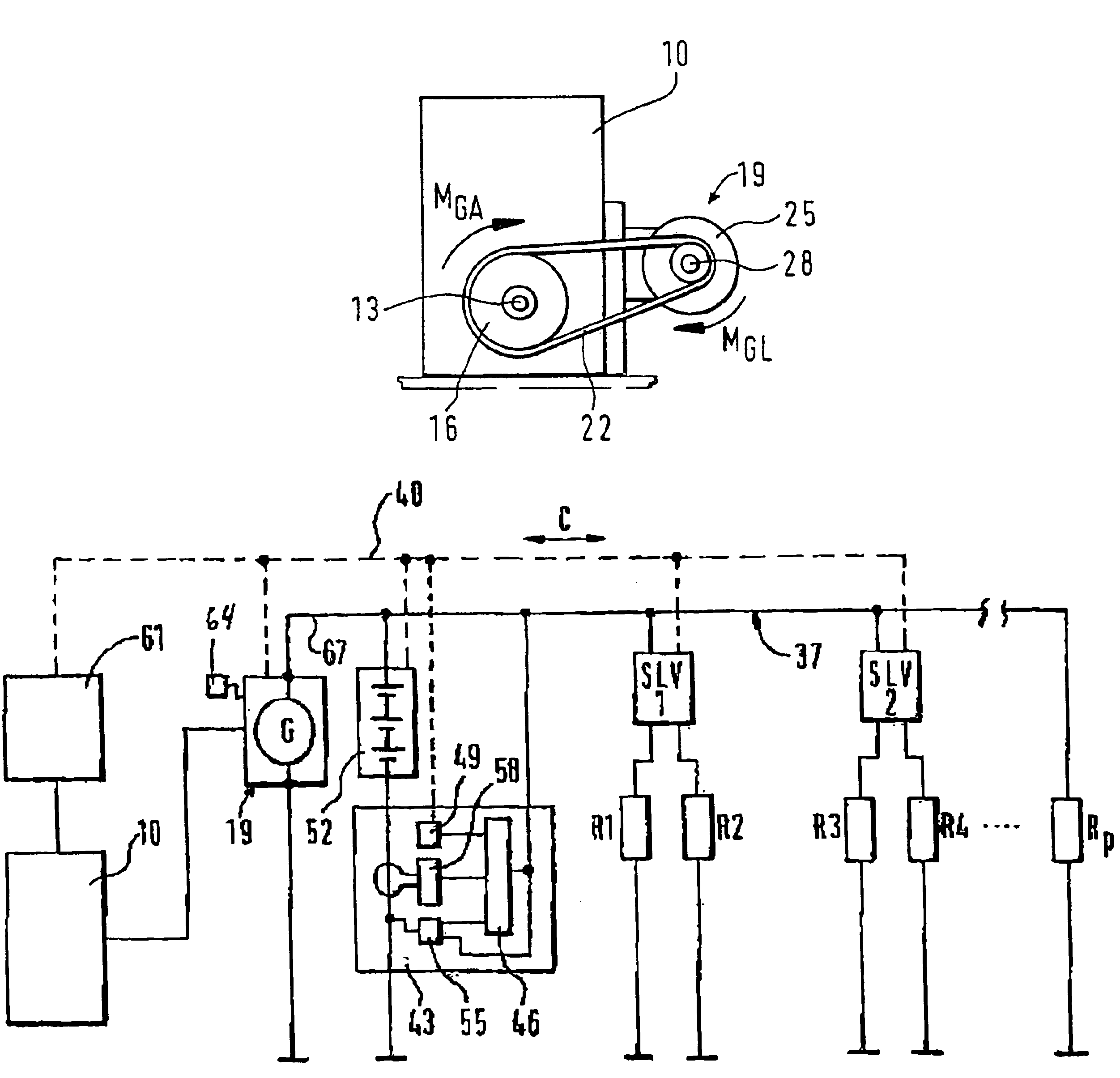
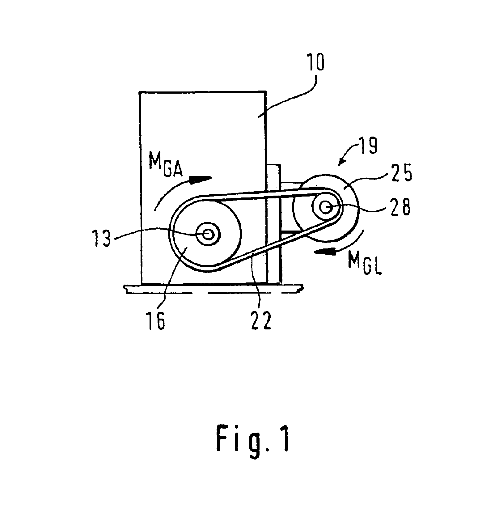
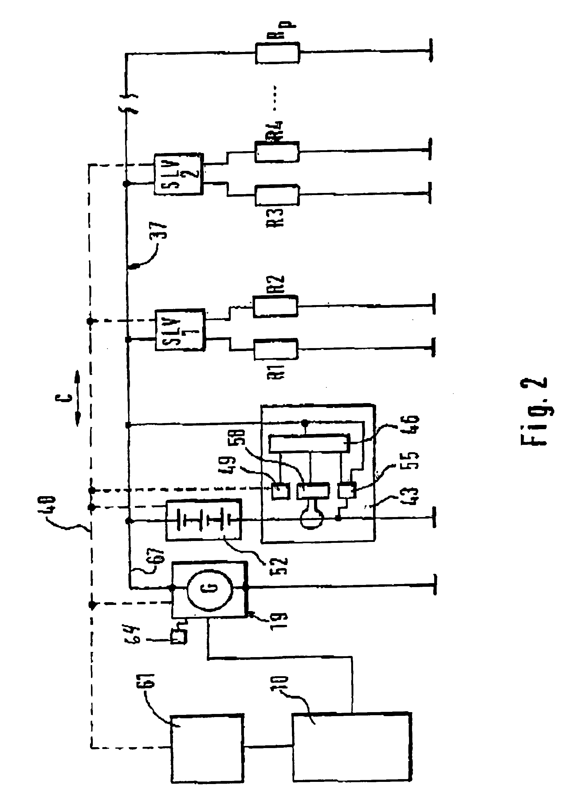
[0015]In FIG. 1, a driving machine 10 is shown, which drives generator 19 via a drive shaft 13 and a drive pulley 16. To that end, the drive pulley 16 is connected to a generator pulley 25 via a belt 22. The generator pulley 25 drives a rotor shaft 28, which with an electromagnetically excited rotor 31 in a stator winding 34 generates an output voltage Us, by which an on-board electrical system 37 is supplied with electrical energy.

[0016]A load torque MGL acting on the generator pulley 25 is created essentially by the electrical system, that is, by the electromagnetic resistances operative there and thus by means of an electrical power PG output by the generator 19.

[0017]The load torque MGL is dependent on the instantaneously output electrical power PG, the generator rpm NG, and the efficiency nG of the generator 19. In order to ascertain the torque MGA exerted on the drive shaft 1...


PUM


Abstract

A method and an apparatus for determining a torque (MGL) of an electrical machine (19), in particular a generator (19) in a motor vehicle, are proposed. The method and the apparatus are characterized in that by a unit (43), the torque (MGL) of the electrical machine (19) is ascertained as a function of a current electrical power (PG) of the generator (19), a current generator rpm (NG), and a current generator efficiency (nG).

Description

BACKGROUND OF THE INVENTION[0001]From the prior art, it is known to ascertain the torque demand of the generator via the electrical power output. The electrical power output of the generator is ascertained from the generated output voltage and the output current of the generator.[0002]Such a direct determination of the electrical generator power is the exception, since because of the attendant high costs a direct current measurement in generators is the exception. Because of the high efficient current intensity that a modern generator furnishes, relatively expensive current measuring instruments are required. It is therefore rare for the torque demand of the generator to be taken into account in the torque balance of the engine controller.SUMMARY OF THE INVENTION[0003]With the method and the apparatus according to the invention, it is possible to ascertain the power and thus the load moment of the generator without measuring the output current.[0004]A prerequisite for determining th...

Claims


Application Information

Patent Timeline
IPC IPC(8): G01L5/24G01L3/02G01L3/16G01L3/22G01L3/24G01L3/26G01L3/14G01L3/00H02P9/00
CPCG01L3/00
Inventor REUTLINGER, KURTSCHMUCKER, CLEMENSBAUMANN, TORSTEN
Owner SEG AUTOMOTIVE GERMANY GMBH
Why Eureka
Try Eureka