
Storage battery state detection apparatus and storage battery state detection method

a storage battery and detection apparatus technology, applied in the direction of engines, engines/engines, instruments, etc., can solve the problems of large fluctuations the inability to normally restart the internal combustion engine in some cases, and the drop in the battery voltage of the storage battery serving as a power supply. to achieve the effect of accurate starting current estimation and precise starting minimum voltag

Active Publication Date: 2016-01-14
MITSUBISHI ELECTRIC CORP
View PDF2 Cites 19 Cited by
  • Summary
  • Abstract
  • Description
  • Claims
  • Application Information

AI Technical Summary

Benefits of technology

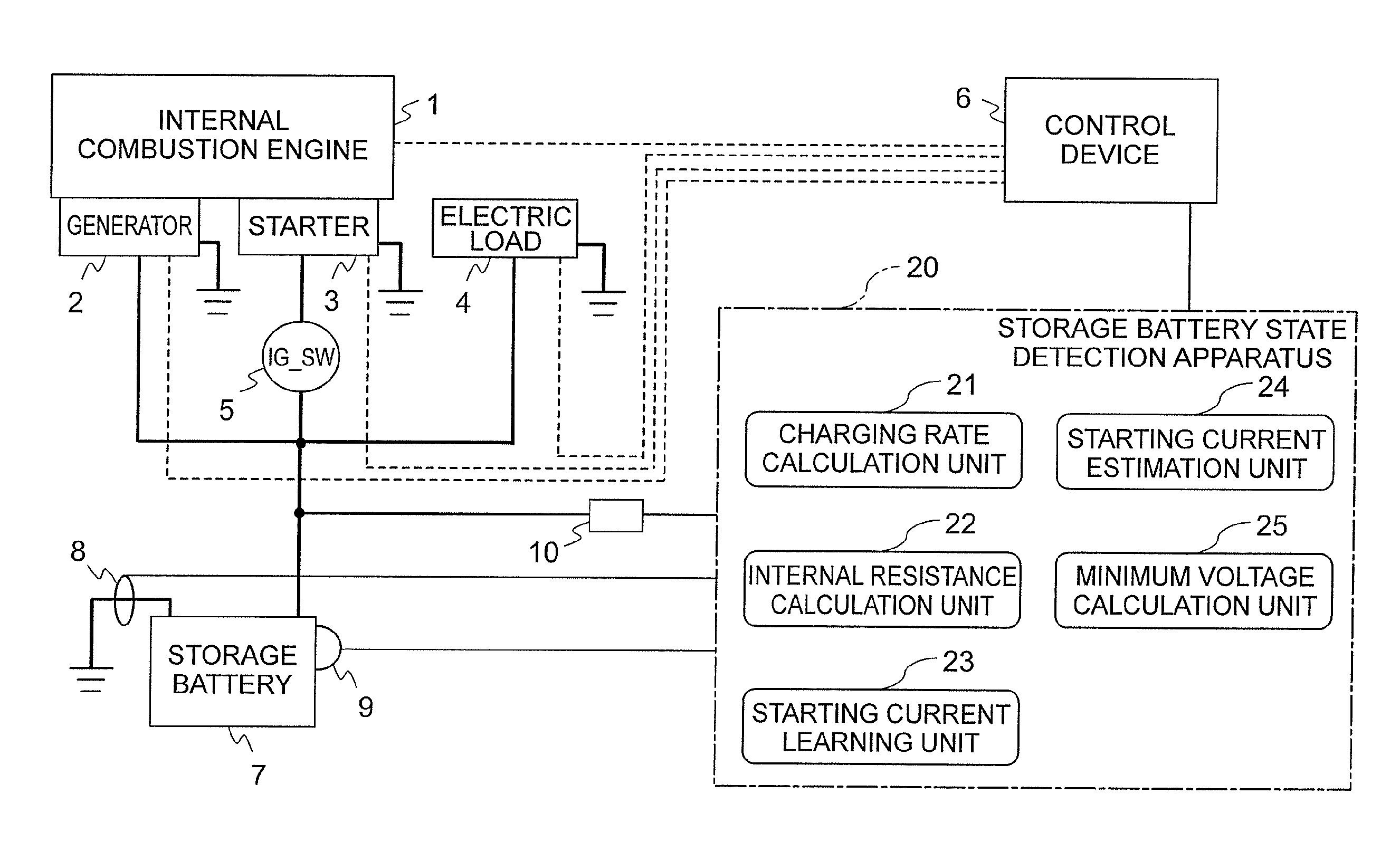
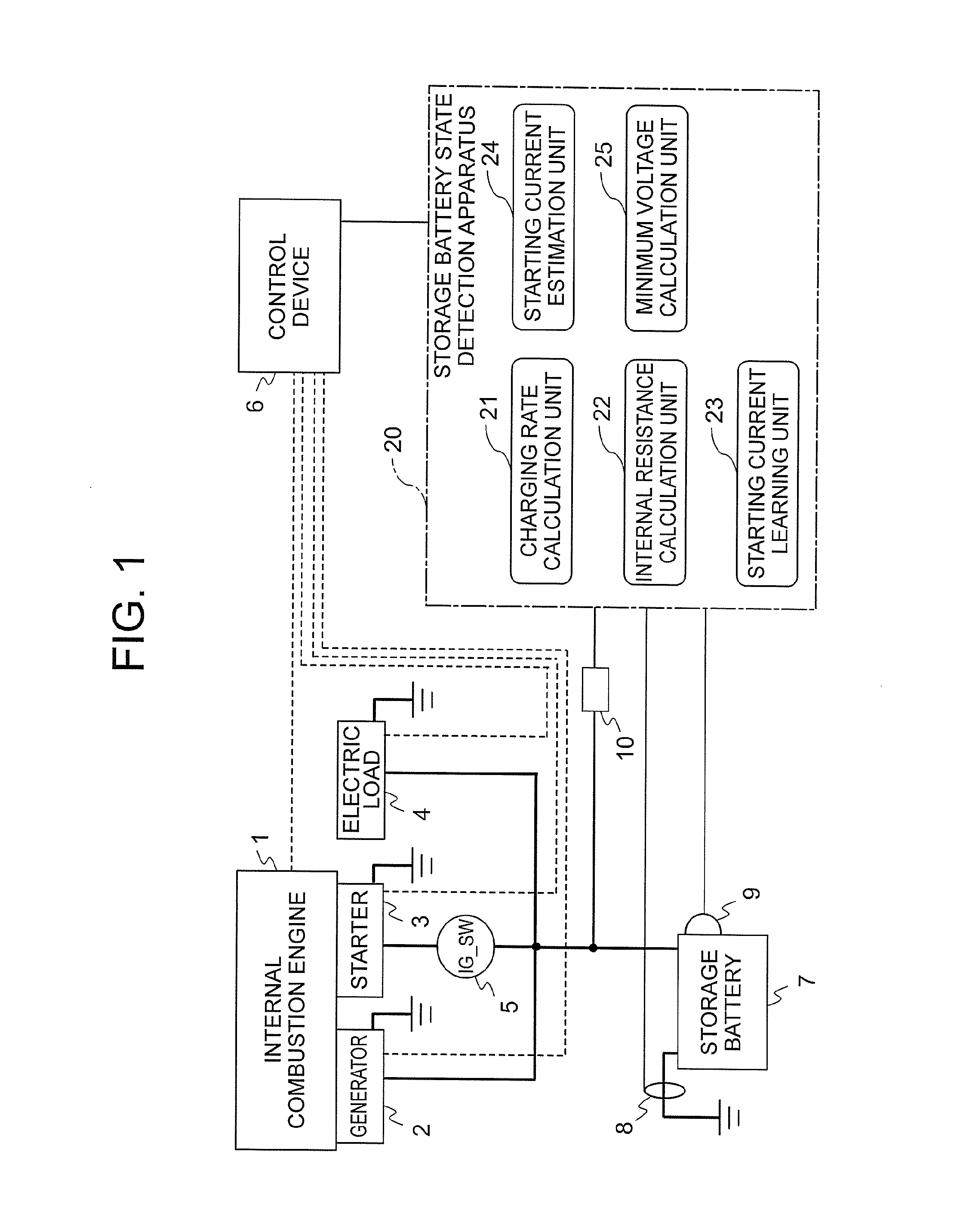
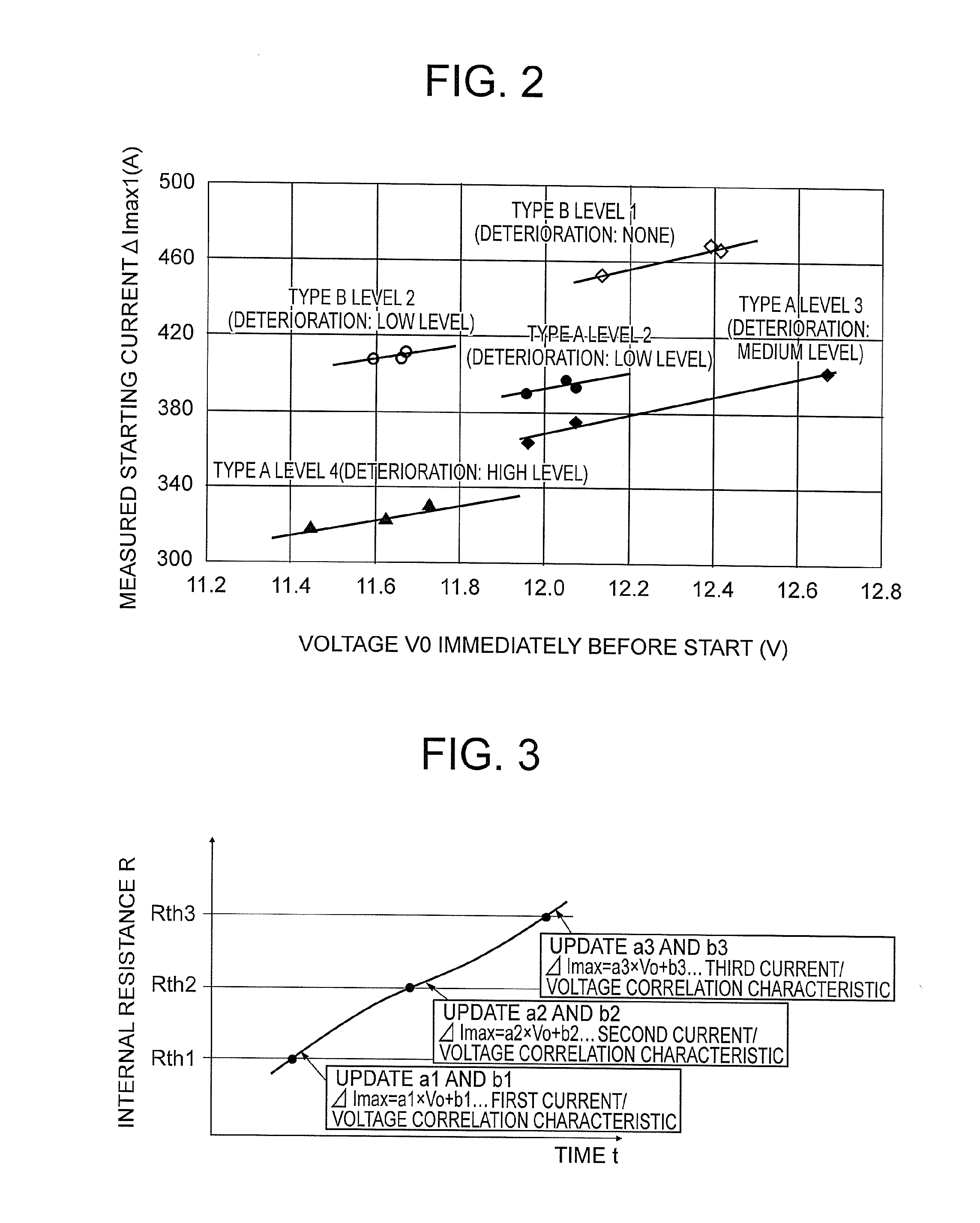
The present invention provides a storage battery state detection apparatus and method that can accurately estimate the starting current and calculate a precise starting minimum voltage, without being influenced by changes in the storage battery state or starting state. This is achieved by updating a current / voltage correlation characteristic corresponding to the deterioration state of the storage battery, and calculating the starting current from the current / voltage correlation characteristic corresponding to the present deterioration state of the storage battery.

Problems solved by technology

In this case, when the internal combustion engine is restarted, a battery voltage of the storage battery serving as a power supply greatly drops due to power consumption of a starting load such as a starter.
Therefore, when the battery voltage of the storage battery greatly drops due to the restart of the internal combustion engine, the ignition device and the control device cannot be appropriately operated, with the result that the internal combustion engine cannot be normally restarted in some cases.
Further, it is known that there are large fluctuations in the battery voltage of the storage battery due to depolarization when a period since a previous time at which the internal combustion engine is automatically stopped until this time at which the internal combustion engine is restarted is within a predetermined period.

Method used


Image

  • Storage battery state detection apparatus and storage battery state detection method
  • Storage battery state detection apparatus and storage battery state detection method
  • Storage battery state detection apparatus and storage battery state detection method

Examples


first embodiment

[0029]First, to clarify a technical feature of the present invention, the above-mentioned problems of the related art are described in detail with reference to FIG. 8. FIG. 8 is a set of explanatory graphs for showing an example of variations with time of a discharge current of a storage battery and a battery voltage thereof that are exhibited while a starter is being driven. Note that, each specific numerical value stated in FIG. 8 merely indicates an example of a value that can be taken by each parameter.

[0030]Now, a case is assumed where, in order to restart an internal combustion engine, by electrically connecting a starting load such as a starter (hereinafter referred to simply as “starter”) to the storage battery, electric power is supplied from the storage battery to drive the starter.

[0031]In such case, as shown in FIG. 8, due to power consumption of the starter, the discharge current of the storage battery sharply increases immediately after the starter is driven, while the...


PUM


Abstract

It is possible to accurately estimate a starting current and calculate a precise starting minimum voltage without being influenced by a change in a storage battery state or a starting state by updating a current / voltage correlation characteristic corresponding to a deterioration state of a storage battery each time a current / voltage data set obtained when a starter is driven is newly stored in association with the deterioration state of the storage battery and by calculating the starting current corresponding to a present voltage immediately before start in accordance with the current / voltage correlation characteristic corresponding to the present deterioration state of the storage battery when determination is made as to whether or not to drive the starter.

Description

TECHNICAL FIELD[0001]The present invention relates to a state detection apparatus for a storage battery for estimating a battery voltage of the storage battery, which is exhibited immediately before a starting load such as a starter for starting an internal combustion engine of a vehicle is driven, and to a state detection method for a storage battery.BACKGROUND ART[0002]In recent years, in regard to a vehicle driven by an internal combustion engine, a system for automatically stopping or restarting the internal combustion engine during driving has been brought to practical use in order to meet a demand for low fuel consumption. Further, there is a need to determine whether or not the storage battery mounted on the vehicle can output electric power necessary to restart the internal combustion engine so as to positively restart the internal combustion engine after being automatically stopped.[0003]Hitherto, in view of the need, a charging state of the storage battery is estimated whe...

Claims


Application Information

Patent Timeline
IPC IPC(8): G01R31/36
CPCG01R31/3662G01R31/3693F02D29/02F02N11/0862F02N2200/06F02N2250/02G01R31/3647G01R31/367G01R31/374G01R31/3842G01R31/389
Inventor SAITO, HIROYUKITANI, HIDEAKIWACHI, SATOSHIHARA, TAKAFUMI
Owner MITSUBISHI ELECTRIC CORP
Learn More