Electroacoustic converter film

a technology of electroacoustic converter and film, applied in the direction of electrical transducers, mechanical vibration separation, instruments, etc., can solve the problem that wiring cannot be connected using soldering or the like, and achieve the effect of ensuring the bending resistance of the electrode lead-out portion

a technology of electroacoustic converter and film, applied in the direction of electrical transducers, mechanical vibration separation, instruments, etc., can solve the problem that wiring cannot be connected using soldering or the like, and achieve the effect of ensuring the bending resistance of the electrode lead-out portion

US20160014527A1Active Publication Date: 2016-01-14FUJIFILM CORP

Image

  • Electroacoustic converter film
  • Electroacoustic converter film
  • Electroacoustic converter film

Examples


Embodiment Construction

[0076]Hereinafter, an electroacoustic converter film of the present invention will be described in detail based on preferred embodiments illustrated in the accompanying drawings.

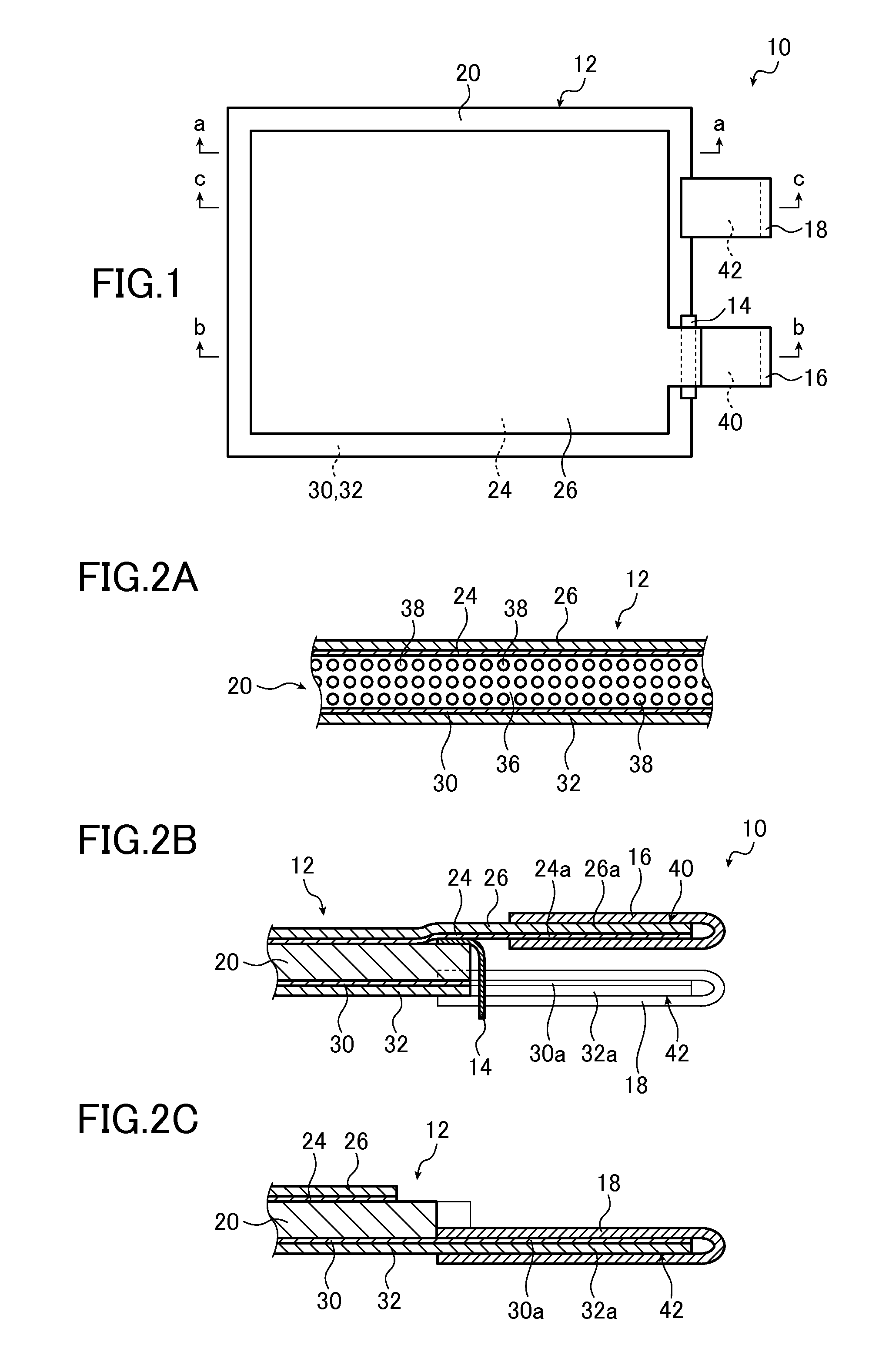
[0077]FIG. 1 conceptually illustrates an example of an electroacoustic converter film (hereinafter referred to as a converter film) of the present invention.

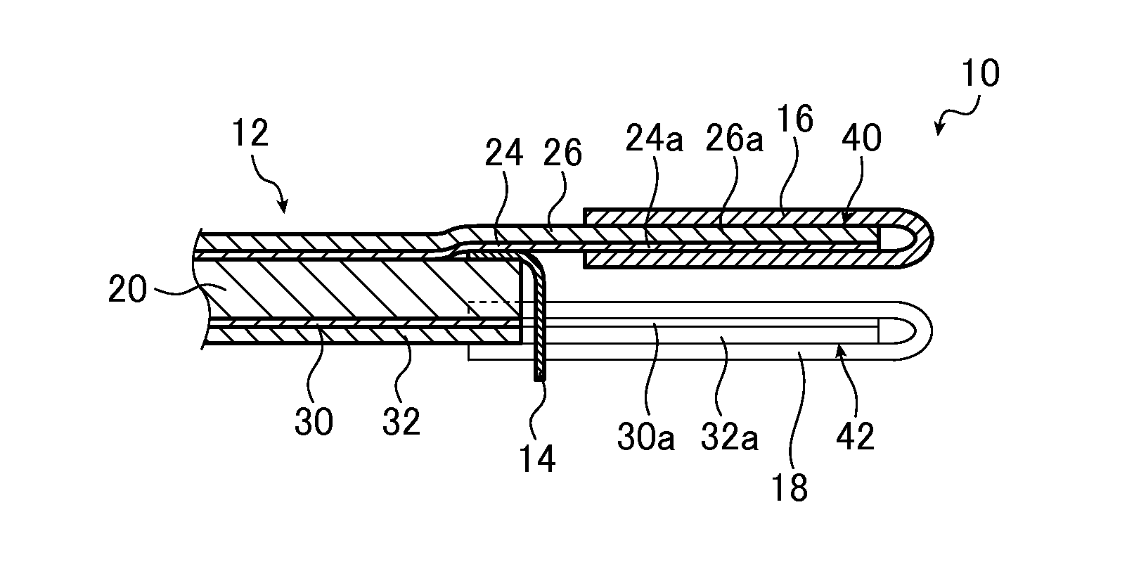
[0078]The (electroacoustic) converter film 10 illustrated in FIG. 1 is basically configured with a piezoelectric laminate 12, an insulating sheet 14, a lead-out metal foil for upper electrode 16, and a lead-out metal foil for lower electrode 18.

[0079]The converter film 10 is used in speakers, microphones, and various acoustic devices (acoustic apparatuses) such as a pickup used for musical instruments including a guitar, for generating (reproducing) sound caused by vibration occurring in response to electric signals, and for converting the vibration caused by sound into electric signals.

[0080]As conceptually illustrated in FIG. 2A, in the converter film ...


PUM

PropertyMeasurementUnit
glass transition temperatureaaaaaaaaaa
frequencyaaaaaaaaaa
temperatureaaaaaaaaaa

Abstract

Provided is an electroacoustic converter film including thin film electrodes provided on both surfaces of a polymeric composite piezoelectric body in which piezoelectric body particles are dispersed in a viscoelastic matrix formed of a polymer material that exhibits viscoelasticity at normal temperature, and protective layers formed on the thin film electrodes. The electroacoustic converter film further includes electrode lead-out metal foils laminated on the thin film electrodes, and the electrode lead-out metal foils allows connection to wiring through soldering when electrodes are led out from the thin film electrodes.

Description

CROSS-REFERENCE TO RELATED APPLICATIONS[0001]This application is a Continuation of PCT International Application No. PCT / JP2014 / 057893 filed on Mar. 20, 2014, which claims priority under 35 U.S.C. ยง119(a) to Japanese Patent Application No. 2013-074481 filed on Mar. 29, 2013. The above application is hereby expressly incorporated by reference, in its entirety, into the present application.BACKGROUND OF THE INVENTION[0002]The present invention relates to an electroacoustic converter film used for, for example, an acoustic device such as a speaker or a microphone. More particularly, the present invention relates to an electroacoustic converter film in which leading out of wiring can be performed easily and reliably at the time of mounting the electroacoustic converter film as the speaker or the like.[0003]In recent years, the research related to flexible displays using a flexible substrate such as plastic has been progressing.[0004]As a substrate of such flexible displays, for example,...

Claims


Application Information

Patent Timeline
14 Jan 2016
Publication
US20160014527A1
IPC
H04R17/00; H10N30/20; H10N30/85; H10N30/87
CPC
H04R2499/11; H04R17/005; B06B1/0662; B06B1/0688; G10K11/004; H04R17/025; H04R2400/00; H10N30/852
Inventors
MIYOSHI, TETSU; HATANAKA, YUSUKE