Eureka AIR delivers breakthrough ideas for toughest innovation challenges, trusted by R&D personnel around the world.

Heat dissipating module and method of combining the same

Inactive Publication Date: 2016-01-14
DELTA ELECTRONICS INC
View PDF24 Cites 8 Cited by
  • Summary
  • Abstract
  • Description
  • Claims
  • Application Information

AI Technical Summary

Benefits of technology

The present invention provides a heat dissipating module and a method of combining it with a circuit board. The module has a heat generating component, like a transistor, installed on the circuit board and penetrated through a through hole. A plate-shaped heat dissipating element is attached to the opposite surface of the circuit board. The heat dissipating element is combined with the through hole by punching, allowing the circuit board, the heat generating component, and the heat dissipating element to be adhered and combined together with the surface mount technology method. The heat dissipating element makes better contact with the heat generating component, providing better heat dissipation performance.

Problems solved by technology

Some manufacturers cool the transistors or other heat generating components by increasing the heat dissipating surface area or the rotating speed of a fan, and thus incurring a higher cost.
In this method, the heat sink or heat dissipating element is separated from the heat generating components by the circuit board, or the heat sink or heat dissipating element is hardly in contact with the transistors or heat generating components, so that the thermal conduction performance is low.

Method used


Image

  • Heat dissipating module and method of combining the same
  • Heat dissipating module and method of combining the same
  • Heat dissipating module and method of combining the same

Examples


Embodiment Construction

[0022]The technical contents of the present invention will become apparent with the detailed description of preferred embodiments accompanied with the illustration of related drawings as follows. It is intended that the embodiments and figures disclosed herein are to be considered illustrative rather than restrictive.

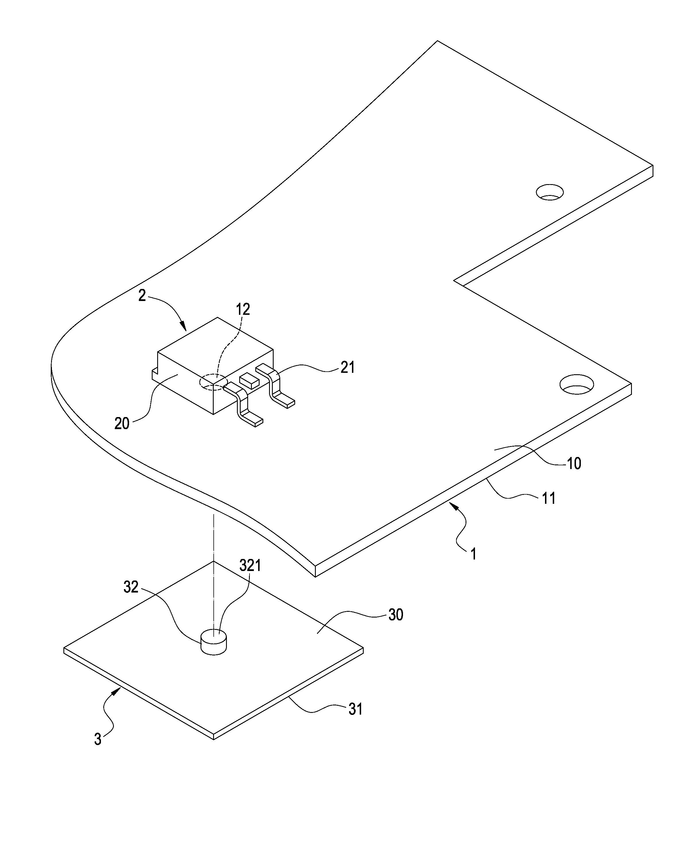
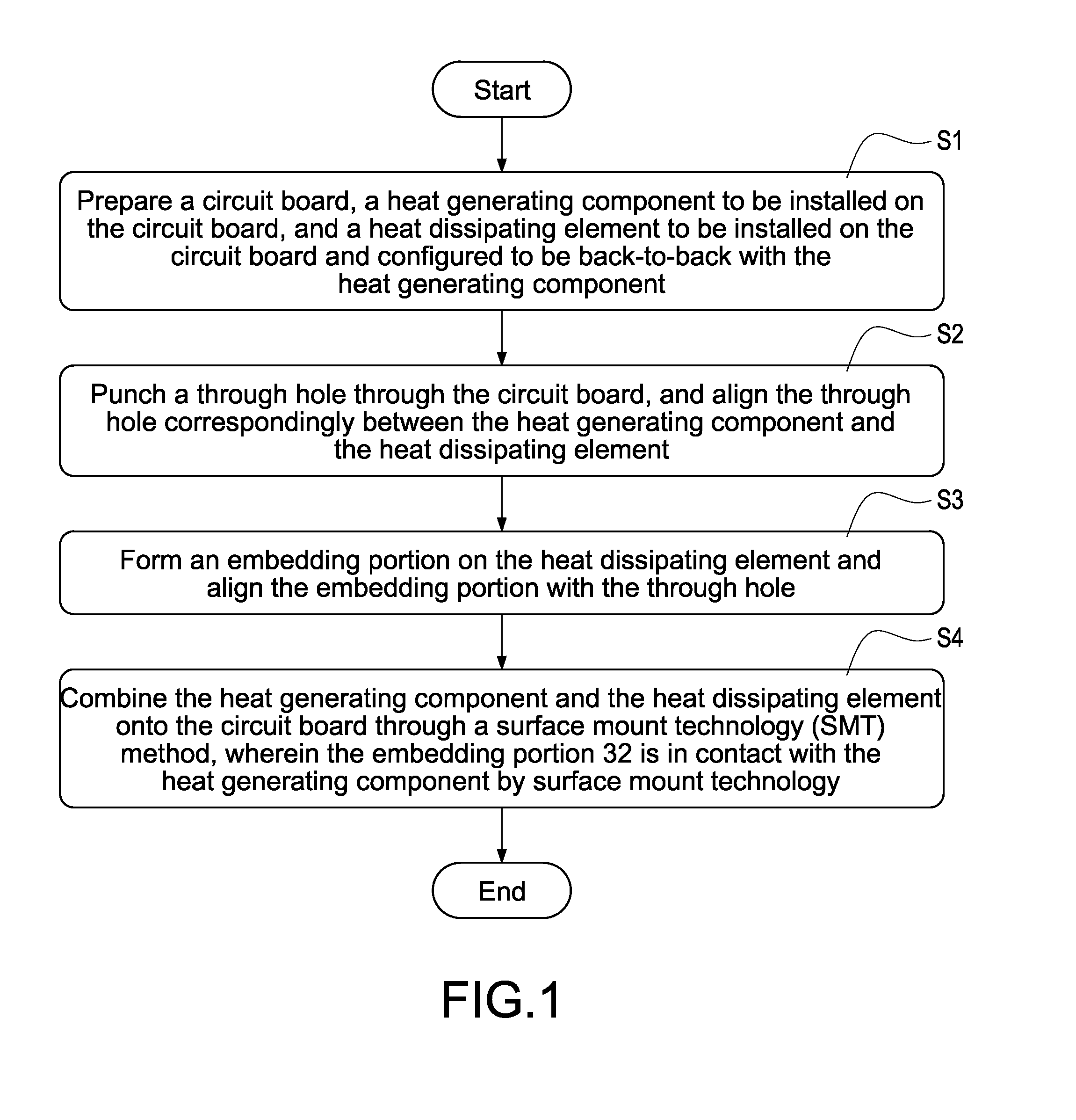
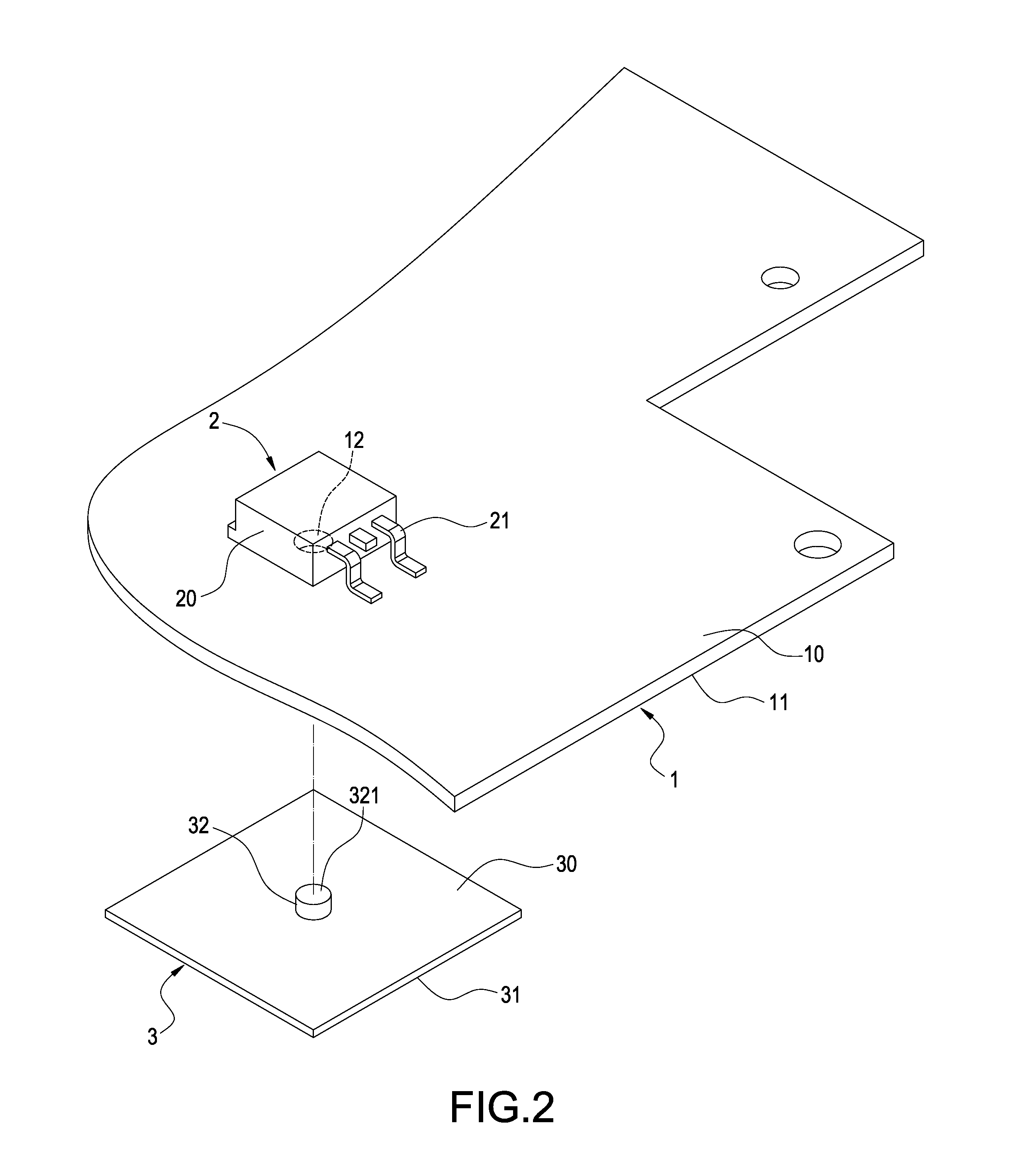
[0023]With reference to FIGS. 1 to 3 for a flow chart of a method of combining a heat dissipating module of the present invention, and an exploded view and a perspective view of the heat dissipating module in accordance with the first preferred embodiment of the present invention respectively, the method of combining the heat dissipating module (as shown in FIG. 1) comprises the following steps:

[0024]S1: Prepare a circuit board 1, a heat generating component 2 to be installed on the circuit board 1, and a heat dissipating element 3 to be installed on the circuit board 1 and configured to be back-to-back with the heat generating component 2. In FIGS. 2 and 3, the circuit...


PUM


Abstract

In a heat dissipating module and a method of combining the heat dissipating module, the heat dissipating module includes a circuit board, a heat generating component, a heat dissipating element, and a surface mount layer. The circuit board has a through hole, and the heat generating component is corresponsive to the through hole and installed on the circuit board, and the heat dissipating element has a protruding embedding portion formed on the other side of the circuit board and embedded into the through hole. The surface mount layer is formed on a surface of the circuit board and the internal periphery of the through hole, and the heat generating component and heat dissipating element are combined with both surfaces of the circuit board respectively, and the heat generating component and the embedding portion are contacted with each other through the surface mount layer.

Description

FIELD OF THE INVENTION[0001]The present invention relates to the heat dissipating technology of a surface mount device (SMD), and more particularly to a heat dissipating module and a method of combining the heat dissipating module with a circuit board and / or heat generating / dissipating components.BACKGROUND OF THE INVENTION[0002]In general, the heat of most heat generating components including surface mount devices (SMD) such as transistors are dissipated by a heat sink or a heat dissipating element attached onto the top surface of the transistors. Since most transistors are made of plastic or an insulation material, therefore the thermal impedance of the transistors is relatively higher, and the heat dissipating effect of the aforementioned heat dissipating method is relatively lower. Some manufacturers cool the transistors or other heat generating components by increasing the heat dissipating surface area or the rotating speed of a fan, and thus incurring a higher cost.[0003]In co...

Claims


Application Information

Patent Timeline
IPC IPC(8): H05K7/20
CPCH05K7/2039
Inventor CHEN, HUNG-CHUANLIAO, SHIH-CHING
Owner DELTA ELECTRONICS INC
Why Eureka
Eureka Blog
Learn More