Vehicle brake system having plunger power source

a technology of power source and brake system, which is applied in the direction of brake system, braking components, transportation and packaging, etc., can solve the problems of increased stopping distance, increased slippage between the wheel and the road surface, and possible loss of directional control

Active Publication Date: 2016-01-21
KELSEY HAYES CO
View PDF7 Cites 16 Cited by
  • Summary
  • Abstract
  • Description
  • Claims
  • Application Information

AI Technical Summary

Problems solved by technology

Under these conditions, a driver can easily apply excessive braking pressure thus causing one or more wheels to lock, resulting in excessive slippage between the wheel and road surface.
Such wheel lock-up conditions can lead to greater stopping distances and possible loss of directional control.
Excessive wheel speed during vehicle acceleration leads to wheel slippage and a loss of traction.
During vehicle motion such as cornering, dynamic forces are generated which can reduce vehicle stability.
Preferably, the hydraulic braking operates in a regenerative brake blending manner so that the blending is effectively and unnoticeably picked up where the electromagnetic braking left off.

Method used


Image

  • Vehicle brake system having plunger power source
  • Vehicle brake system having plunger power source
  • Vehicle brake system having plunger power source

Examples


first embodiment

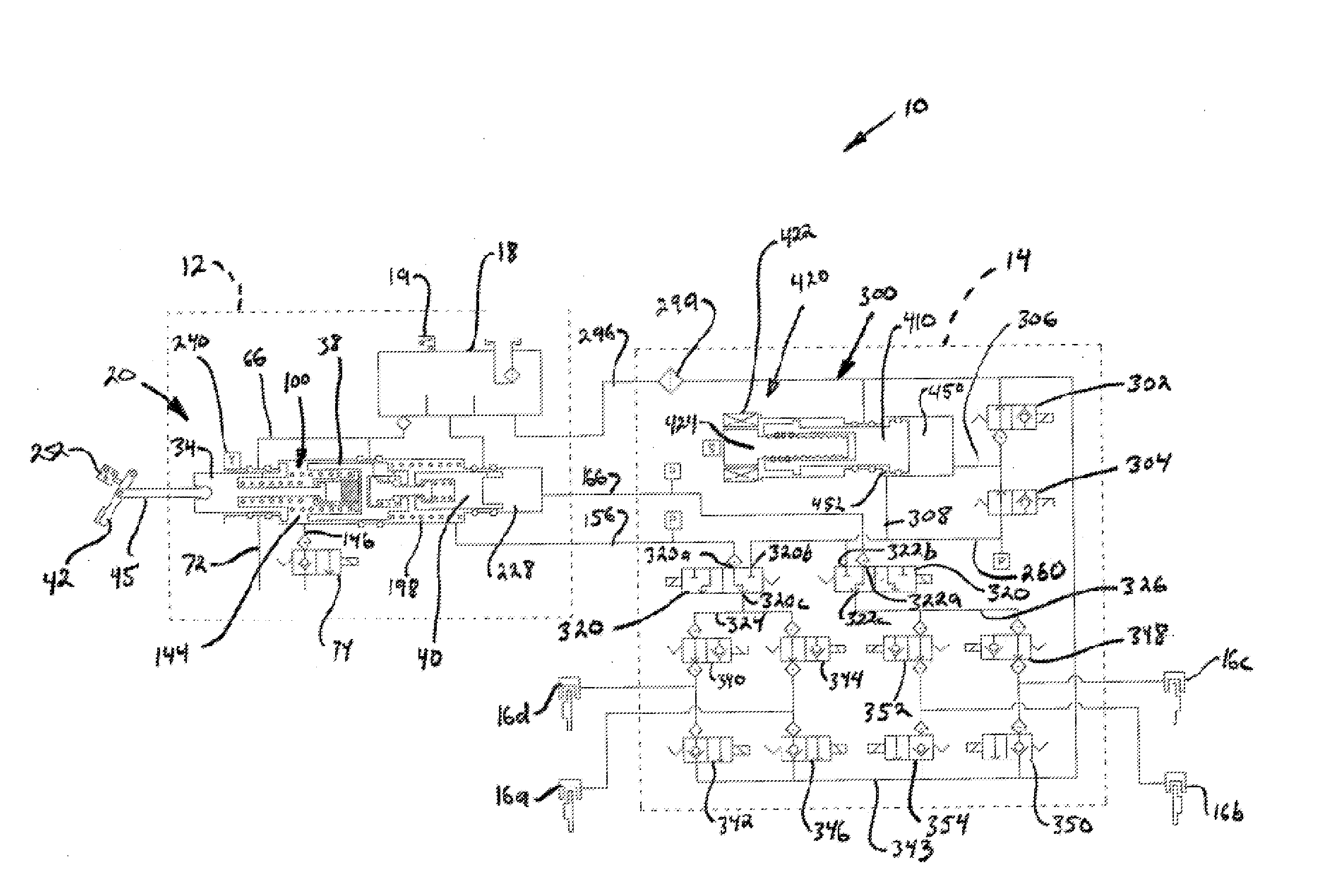
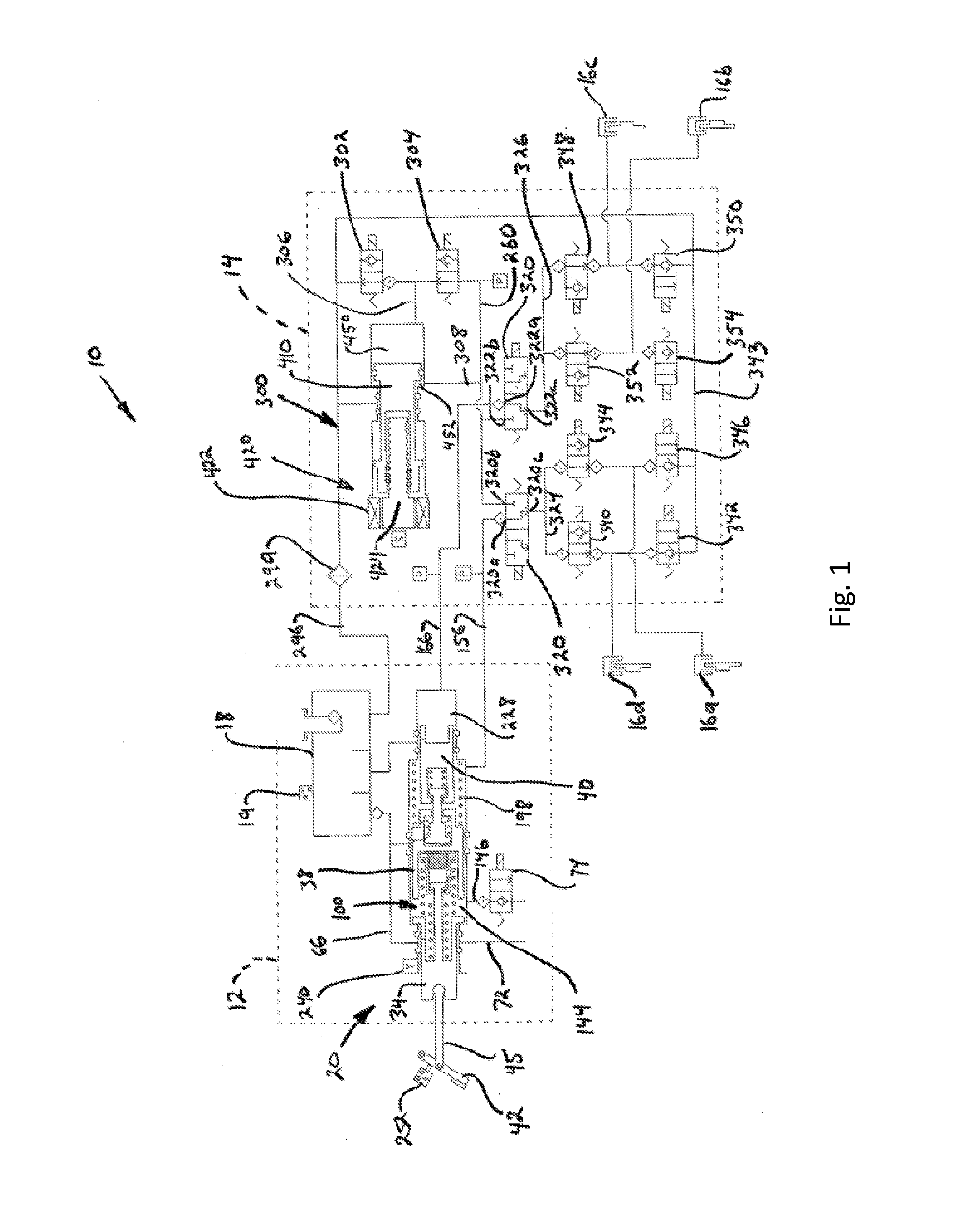
[0035]Referring now to the drawings, there is schematically illustrated in FIG. 1 a vehicle brake system, indicated generally at 10. The brake system 10 is a hydraulic boost braking system in which boosted fluid pressure is utilized to apply braking forces for the brake system 10. The brake system 10 may suitably be used on a ground vehicle such as an automotive vehicle having four wheels with a wheel brake associated with each wheel. Furthermore, the brake system 10 can be provided with other braking functions such as anti-lock braking (ABS) and other slip control features to effectively brake the vehicle, as will be discussed below.

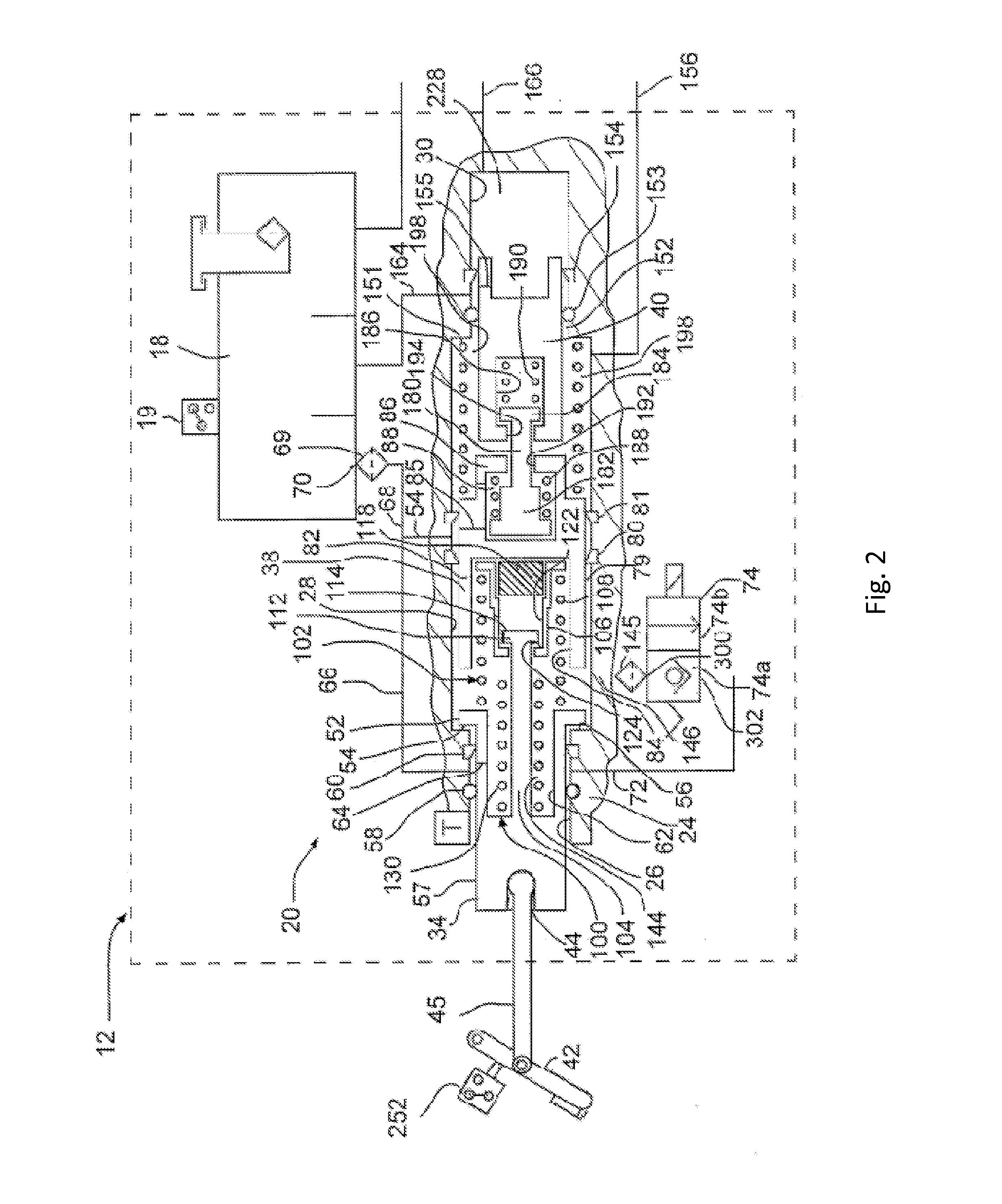
[0036]The brake system 10 generally includes a first block or brake pedal unit assembly, indicated by broken lines 12, and a second block or hydraulic control unit, indicated by broken lines 14. The various components of the brake system 10 are housed in the brake pedal unit assembly 12 and the hydraulic control unit 14. The brake pedal unit assembly 12...

second embodiment

[0083]There is illustrated in FIG. 5 a schematic illustration of a brake system, indicated generally at 600. The brake system 600 is similar to the brake system 10 of FIG. 1 and, therefore, like functions and structures will not be described. Similar to the brake system 10, the brake system 600 includes a brake pedal unit 612, a hydraulic control unit 614, and wheel brakes 616a-d.

[0084]The brake system 600 does not include a venting valve like the venting valve 302 of the system 10. Instead, the brake system 600 includes a plunger assembly 620 similar to the plunger assembly 300. One of the differences is that the plunger assembly 620 has a piston 622 with a check valve 624 mounted therein. The check valve 624 permits fluid to flow from a first pressure chamber 630 to a reservoir conduit 632 (in communication with a reservoir 613) via a conduit 634 within the piston 622. It is noted that the check valve 624 prevents the flow of fluid from the reservoir 613 to the first pressure cha...

third embodiment

[0095]There is illustrated in FIG. 7 a schematic illustration of a brake system, indicated generally at 800. The brake system 800 is similar to the brake system 600 and, therefore, like functions and structures will not be described. The brake system 10 is ideally suited for large passenger vehicles or trucks. Generally, larger vehicles require more braking power and more fluid volume than brake systems for smaller vehicles. This generally requires a larger consumption of power for the motor for the plunger assembly.

[0096]The brake system 800 includes a brake pedal unit 812, a hydraulic control unit 814, and wheel brakes 816a-d. The brake assembly 800 further includes a plunger assembly 820 having a piston 822 with a check valve 824 mounted therein. The check valve 824 permits fluid to flow from a first pressure chamber 830 to a reservoir conduit 832 (in communication with a reservoir 813) via a conduit 834 within the piston 822. The check valve 824 prevents the flow of fluid from t...


PUM


Abstract

A brake system includes first and second wheel brakes, a reservoir, and a brake pedal unit having a housing and a pair of output pistons slidably disposed in the housing. The output pistons generate brake actuating pressure during a manual push-through mode for actuating the first and second wheel brakes. The system further includes a plunger assembly having a housing having first and second ports, a motor driving an actuator, and a piston connected to the actuator. The piston pressurizes a first chamber when the piston is moving in a first direction to provide fluid flow out of the first port. The piston pressurizes a second chamber when the piston is moving in a second direction opposite the first direction to provide fluid flow out of the second port. The first and second ports are selectively in fluid communication with the wheel brakes.

Description

CROSS-REFERENCE TO RELATED APPLICATIONS[0001]This application is a continuation-in-part patent application of U.S. patent application Ser. No. 13 / 843,587, filed Mar. 15, 2013, the disclosure of which is incorporated herein by reference in its entirety. This application also claims the benefit of U.S. Provisional Application No. 62 / 055,698, filed Sep. 26, 2014, and U.S. Provisional Application No. 62 / 068,134, filed Oct. 24, 2014, the disclosures of which are incorporated herein by reference in their entirety.BACKGROUND OF THE INVENTION[0002]This invention relates in general to vehicle braking systems. Vehicles are commonly slowed and stopped with hydraulic brake systems. These systems vary in complexity but a base brake system typically includes a brake pedal, a tandem master cylinder, fluid conduits arranged in two similar but separate brake circuits, and wheel brakes in each circuit. The driver of the vehicle operates a brake pedal which is connected to the master cylinder. When th...

Claims


Application Information

Patent Timeline
Patent Type & Authority Applications(United States)
IPC IPC(8): B60T13/16B60T7/04B60T8/40B60T13/74
CPCB60T13/168B60T7/042B60T13/166B60T8/4081B60T13/745B60T8/4018
Inventor GANZEL, BLAISE, J.
Owner KELSEY HAYES CO
Why Eureka
Try Eureka