
System and flow adaptive sensorless pumping control apparatus for energy saving pumping applications

Active Publication Date: 2016-01-21
FLUID HANDLING
View PDF3 Cites 25 Cited by
  • Summary
  • Abstract
  • Description
  • Claims
  • Application Information

AI Technical Summary

Benefits of technology

This patent describes a new system and technique for controlling hydronic pumps in heating and cooling systems. The system is adaptive, meaning it can adjust to changes in the flow rate of the system and the pressure needed to maintain the flow rate. This results in an energy-efficient control system that saves energy by optimizing the pumping process. This system and technique offer an important contribution to the development of hydronic pumping heating and cooling systems that are more energy-efficient and cost-effective.

Problems solved by technology

Following this configuration, there is significant energy waste in the system, including the energy loss due to flow dynamic friction through the bypass pipelines and valves, as well as the water thermal energy loss in bypass lines.
However, the amount of energy that might be saved by these energy saving control means or techniques is mostly dependent on the control parameters set up, for instance, system design values on pressure and flow rate which are unknown in general to an operator due to the complexity of a hydronic system in service.

Method used


Image

  • System and flow adaptive sensorless pumping control apparatus for energy saving pumping applications
  • System and flow adaptive sensorless pumping control apparatus for energy saving pumping applications
  • System and flow adaptive sensorless pumping control apparatus for energy saving pumping applications

Examples


Embodiment Construction

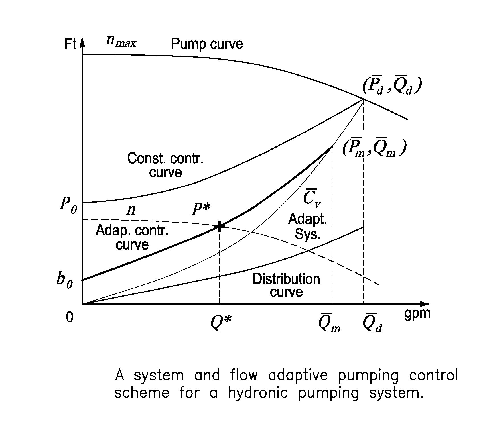
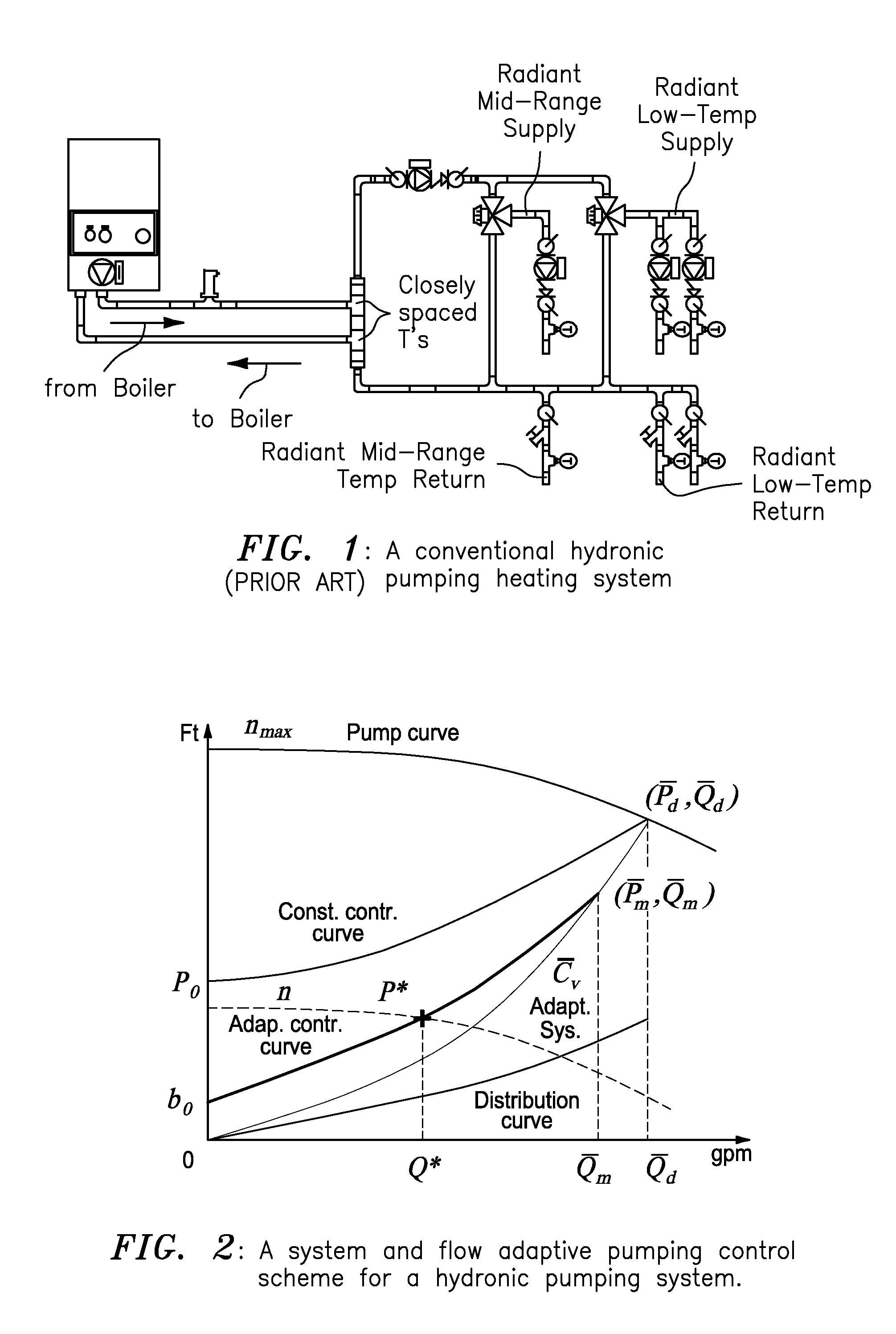
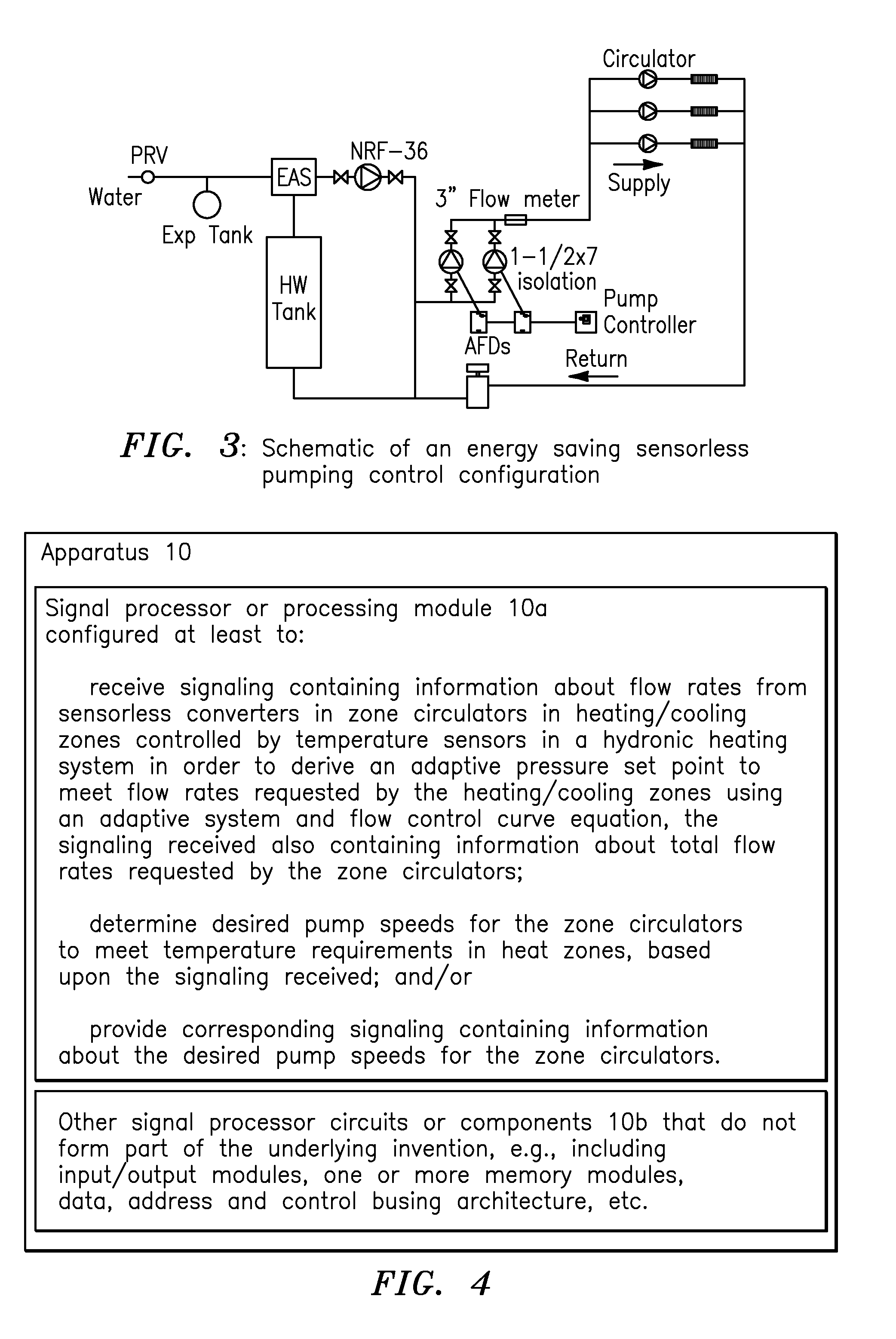
[0019]According to some embodiments, the present invention may include, or take the form of, apparatus featuring a signal processor or processing module configured at least to:[0020]receive signaling containing information about flow rates from sensorless converters in zone circulators in heating / cooling zones controlled by temperature sensors in a hydronic heating system in order to derive an adaptive pressure set point to meet the flow rates requested by the heating / cooling zones using an adaptive system and flow control curve equation, the signaling received also containing information about total flow rates requested by the zone circulators; and[0021]determine desired pump speeds for the zone circulators to meet temperature requirements in heat zones, based upon the signaling received.

[0022]According to some embodiments, the present invention may include one or more of the following features:

[0023]The signal processor or processing module may be configured to provide correspondi...


PUM


Abstract

A signal processor receives signaling containing information about flow rates from sensorless converters in zone circulators in heating / cooling zones controlled by temperature sensors in a hydronic heating system in order to derive an adaptive pressure set point to meet the flow rates requested by the heating / cooling zones using an adaptive system and flow control curve equation, the signaling containing information about total flow rates requested by the zone circulators; determines desired pump speeds for the zone circulators to meet temperature requirements in heat zones; provides corresponding signaling containing information about the desired pump speeds; and / or determines the adaptive pump control curve equation based upon an adaptive system curve and as a moving maximum system flow rate depending on an adaptive pressure set point, a system flow rate requested by temperature loads, a minimum pressure at no flow, a control curve setting parameter, and an adaptive moving maximum flow and pressure.

Description

CROSS REFERENCE TO RELATED APPLICATION[0001]This application claims benefit to U.S. provisional application No. 62 / 007,474 (Atty Dckt No. 911-019.015-1 / / F-B&G-X0013US), filed 4 Jun. 2014, entitled “System and Flow Adaptive Pumping Control Apparatus—A Minimum Pumping Energy Operation Control System vs. Sensorless Application,” which is hereby incorporated by reference in its entirety.[0002]This application is also related to a family of technologies developed by one or more of the inventors herein, and disclosed in the following applications:[0003][1] U.S. application Ser. No. 12 / 982,286 (Atty Dckt No. 911-019.001-1 / / F-B&G-1001), filed 30 Dec. 2010, entitled “Method and apparatus for pump control using varying equivalent system characteristic curve, AKA an adaptive control curve,” which issued as U.S. Pat. No. 8,700,221 on 15 Apr. 2014;[0004][2] U.S. application Ser. No. 13 / 717,086 (Atty Dckt No. 911-019.004-2 / / F-B&G-X0001), filed 17 Dec. 2012, entitled “Dynamic linear control method...

Claims


Application Information

Patent Timeline
IPC IPC(8): F04D27/00F24F11/00G05B13/04
CPCF04D27/00G05B13/041F24F11/006F04D15/0072F24F11/83F24F11/85
Inventor CHENG, ANDREW A.GU, JAMES J.SCOTT, GRAHAM A.
Owner FLUID HANDLING
Learn More