
Component mounting method and component mounting system

a technology of component mounting and mounting system, which is applied in the direction of analogue processes, instruments, manufacturing tools, etc., can solve the problems of difficult to predict the effectiveness of countermeasures, inability to confirm specific details of influence, and inability to secure a good productivity

Inactive Publication Date: 2016-01-21
PANASONIC INTELLECTUAL PROPERTY MANAGEMENT CO LTD
View PDF5 Cites 11 Cited by
  • Summary
  • Abstract
  • Description
  • Claims
  • Application Information

AI Technical Summary

Benefits of technology

The present invention aims to provide a method and system for mounting components that can improve production efficiency by addressing changes in component data. This can result in increased productivity and better overall performance of the production process.

Problems solved by technology

However, in the technique example disclosed in JP-A-2007-059563, it is possible to confirm a production program that may be influenced by the change of the component data, but it is not possible to confirm specific details of the influence.
Therefore, even when the change of the component data causes an adverse effect on a production efficiency such as delay of the production cycle time, it is hard to predict what countermeasure is effective, and it is impossible, as a consequence, to secure a good productivity.

Method used


Image

  • Component mounting method and component mounting system
  • Component mounting method and component mounting system
  • Component mounting method and component mounting system

Examples


Embodiment Construction

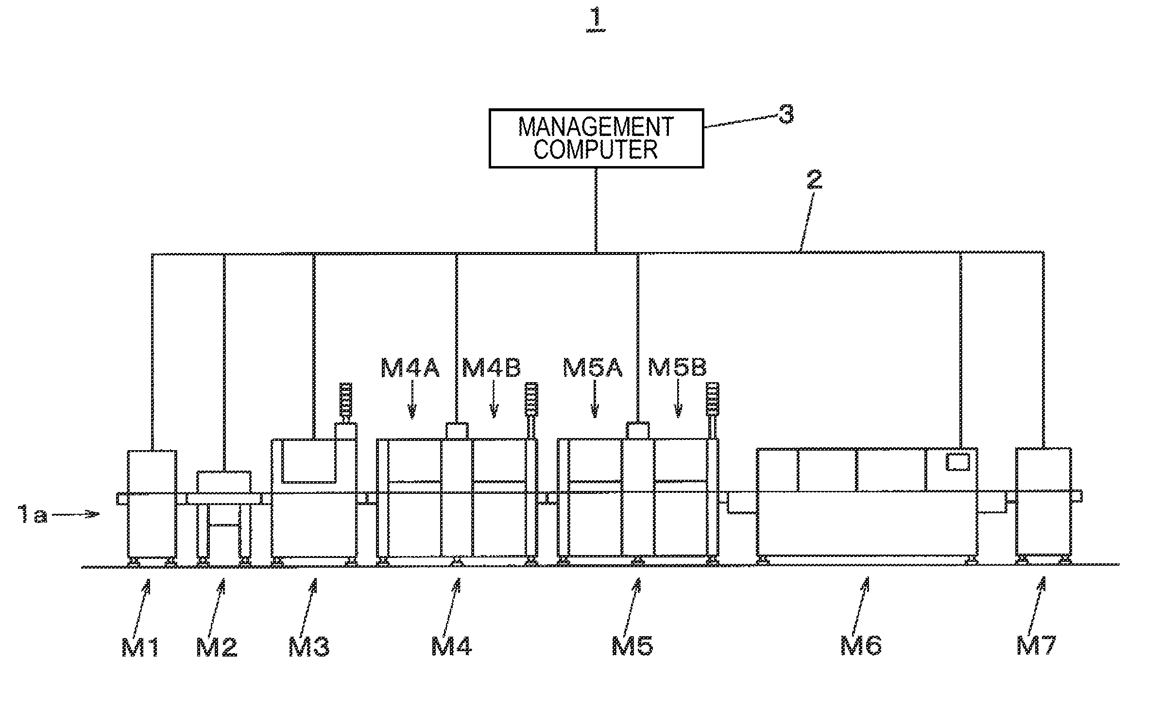
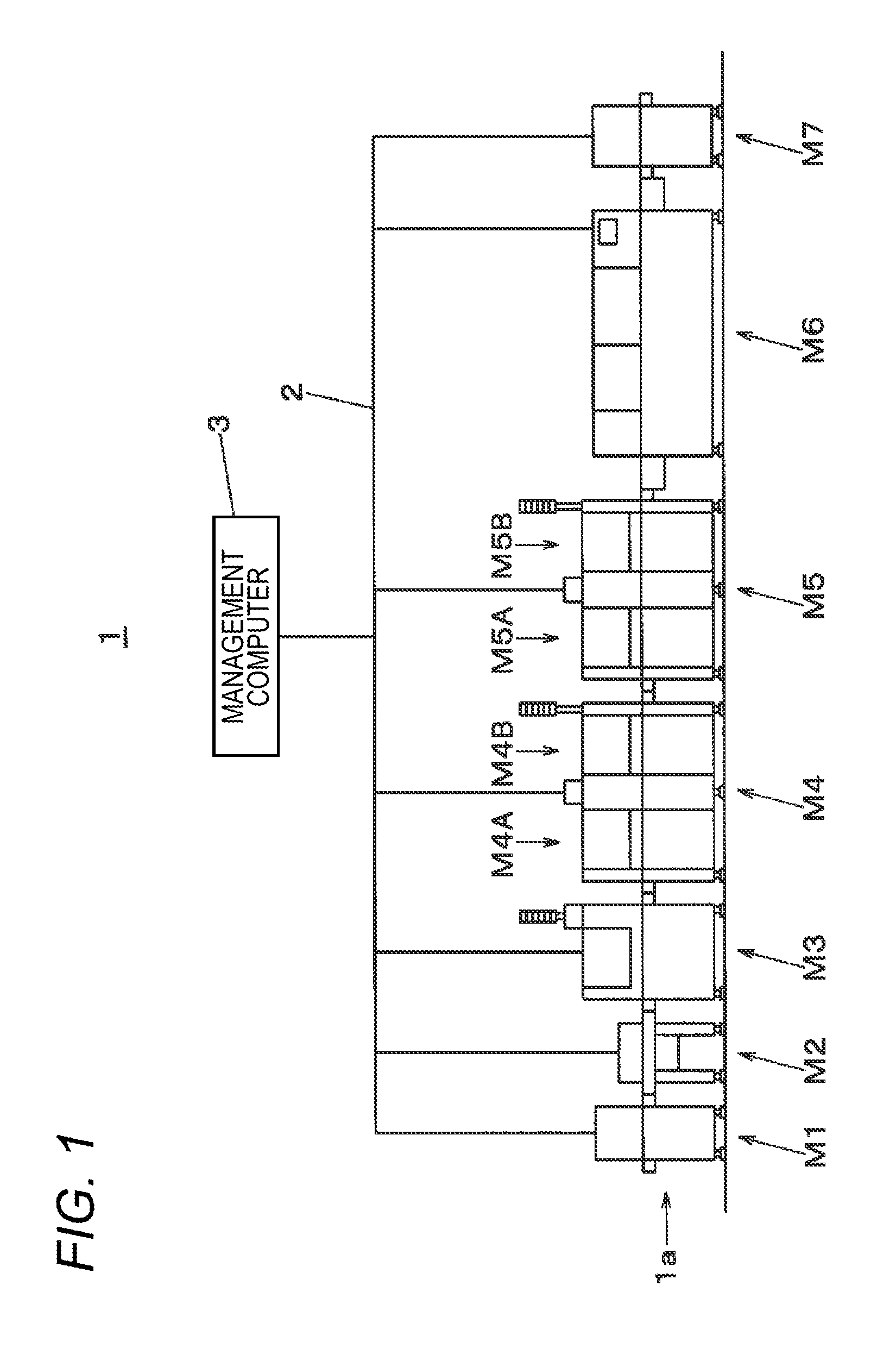
[0026]Embodiments of the present invention will be described with reference to the accompanying drawings. First, a configuration of a component mounting system 1 will be described with reference to FIG. 1. The component mounting system 1 has a function of mounting an electronic component onto a board to produce a component-mounted board, and provides a component mounting line 1a having a configuration in which a board supplying apparatus M1, a board transfer apparatus M2, a solder printer M3, component mounting apparatuses M4 and M5 having the same configuration, a reflow apparatus M6, and a board receiving apparatus M7 are connected in series, as a main body. Each apparatus of the board supplying apparatus M1 to the board receiving apparatus M7 is connected to a management computer 3 through a communication network 2.

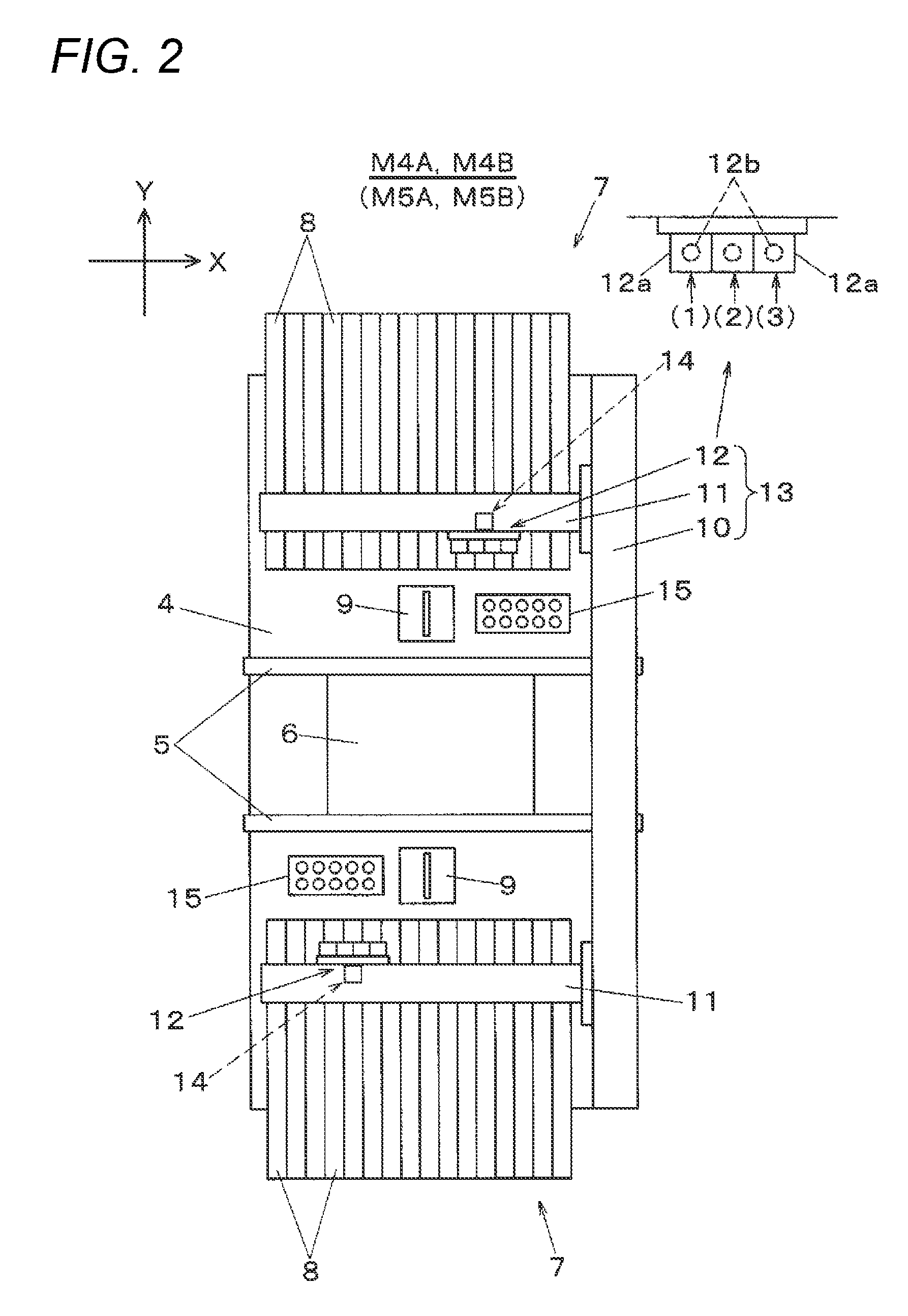
[0027]A board6 (see FIG. 2) supplied by the board supplying apparatus M1 is carried into the solder printer M3 through the board transfer apparatus M2, and in the sold...


PUM


Abstract

A component mounting method is provided in a component mounting apparatus that mounts a component onto a board using a plurality of pieces of production data linked to component data. The method includes executing, when the component data is changed, a simulation of a production cycle time based on the production data, and making an improvement plan for the production cycle time as a target based on a simulation result after change of the component data, and outputting the improvement plan.

Description

CROSS-REFERENCES TO RELATED APPLICATION(S)[0001]This application is based on and claims priority from Japanese Patent Application No. 2014-146440 filed on Jul. 17, 2014, the entire contents of which are incorporated herein by reference.BACKGROUND[0002]1. Field of the Invention[0003]The present invention relates to a component mounting method and a component mounting system that mount a component onto a board.[0004]2. Description of Related Art[0005]In a component mounting system that produces a component-mounted board, plural types of electronic components are mounted onto a board by a component mounting apparatus. In such a mounting operation, component data that is set in advance according to a component which is a mounting target is referred to. The component data includes, for example, a variety of data such as a speed parameter that regulates, for each component, a suction speed in suctioning and extracting the component by a mounting head, a mounting speed in mounting the extr...

Claims


Application Information

Patent Timeline
IPC IPC(8): H05K13/04G06F17/50H05K3/30
CPCH05K13/046H05K3/301H05K2203/16H05K2203/163G06F17/5009G06F30/20H05K13/085
Inventor IWATA, ISATOTAKEHARA, HIROKAZUYAMAZAKI, TAKUYASAGARA, HIROKI
Owner PANASONIC INTELLECTUAL PROPERTY MANAGEMENT CO LTD
Learn More