Aircraft landing gear

Active Publication Date: 2016-01-28
AIRBUS OPERATIONS LTD
View PDF9 Cites 10 Cited by
  • Summary
  • Abstract
  • Description
  • Claims
  • Application Information

AI Technical Summary

Benefits of technology

The present invention provides a more efficient and compact landing gear system for aircraft. It uses multiple leaf springs that are positioned remotely from the sprung arm, which reduces loads and stress levels in each individual leaf spring. A swinging link connects the leaf springs to the transfer arm, which enables the leaf springs to be positioned in a way that maximizes space usage and distributes loads effectively into the airframe. The use of a crank arm further expands the positioning options for the swinging link. A stop prevents excessive rotation of the sprung arm. The leaf springs remain in a plane as they bend, which makes the arrangement more compact than if they bend out of the plane. Overall, this landing gear system provides a more efficient and reliable solution for aircraft.

Problems solved by technology

It may be difficult to design a leaf spring that is capable of supporting ground load for a large aircraft.

Method used


Image

  • Aircraft landing gear
  • Aircraft landing gear
  • Aircraft landing gear

Examples


Embodiment Construction

)

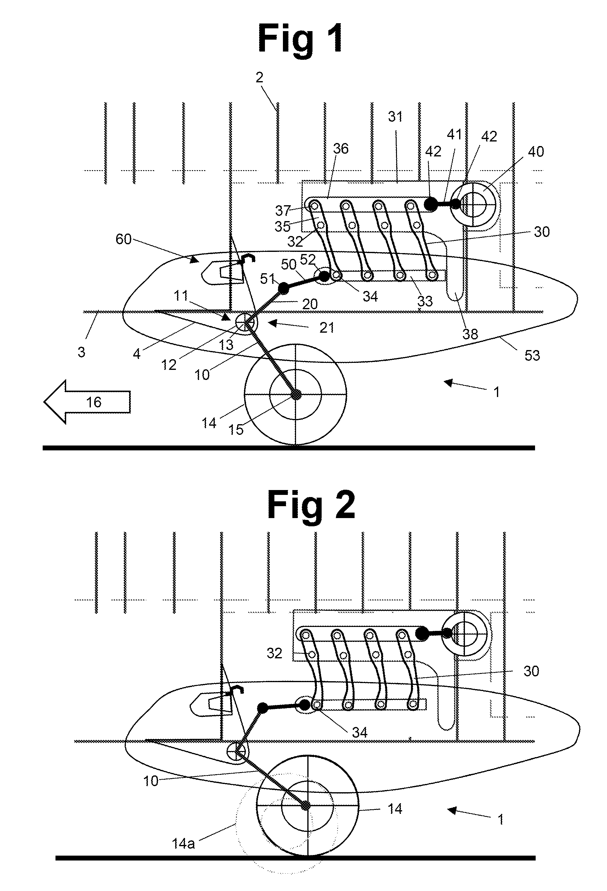
[0040]FIG. 1 is a schematic side view of an aircraft landing gear 1 mounted to the fuselage of an aircraft. The fuselage comprises a series of hooped ribs 2 which are spaced apart fore and aft and carry a fuselage skin 3 and a mounting bracket 4. A sprung arm 10 is mounted to the mounting bracket 4 by a main pivot 11. The main pivot 11 comprises a main pivot shaft 12 which can rotate about a main pivot axis 13 which extends normal to the plane of FIG. 1. The sprung arm 10 carries a pair of wheels 14 (only one wheel being visible in FIG. 1) each having a wheel axis 15 which, like the main pivot axis 13, extends normal to the plane of FIG. 1. The sprung arm 10 is a trailing arm which is angled to the rear relative to a direction of motion 16 of the aircraft so that when the aircraft touches down, the ground loads cause the sprung arm 10 to rotate up about the main pivot axis 13 (anti-clockwise from the viewing direction of FIG. 1).

[0041]A crank arm 20 is also carried by the main pivo...


PUM


Abstract

An aircraft landing gear including: a sprung arm mounted to a main pivot and carrying one or more wheels; leaf springs; a transfer arm attached to each of the leaf springs; and a swinging link with a first end which is pivotally coupled to the sprung arm via a first swinging link pivot and a second end which is pivotally coupled to the transfer arm via a second swinging link pivot. The leaf springs are arranged to provide a resilient biasing force via the transfer arm and the swinging link which opposes rotation of the sprung arm about the main pivot. Each leaf spring only absorbs a portion of the landing loads, so load and stress levels in each individual spring are lower. The swinging link enables the leaf springs to be positioned remotely from the sprung arm, in a suitable position to optimise the use of space and distribute loads efficiently into the airframe.

Description

RELATED APPLICATION[0001]This application claims priority of United Kingdom (GB) Application Number 1413133.8 filed on 24 Jul. 2014, the entirety of which is incorporated by reference.FIELD OF THE INVENTION[0002]The present invention relates to a landing gear with a leaf spring for absorbing ground load.BACKGROUND OF THE INVENTION[0003]A landing gear with a composite leaf spring is described in U.S. Pat. No. 8,640,988. The landing gear comprises an arm mounted to a pivot and carrying one or more wheel assemblies; and a composite leaf spring which is coupled to the arm and arranged to provide a resilient biasing force which opposes rotation of the arm about the pivot. A support carries the pivot, and a proximal end of the leaf spring is coupled to the support via a swinging link which reduces tensile forces in the spring.[0004]It may be difficult to design a leaf spring that is capable of supporting ground load for a large aircraft.SUMMARY OF THE INVENTION[0005]A first aspect of the ...

Claims


Application Information

Patent Timeline
IPC IPC(8): B64C25/20
CPCB64C25/20B64C25/14B64C25/18B64C25/58B64C25/62
Inventor THOMPSON, ROBERT, IAN
Owner AIRBUS OPERATIONS LTD
Why Eureka
Try Eureka