Non-cylindrical damping element suspension

a damping element and non-cylindrical technology, which is applied in the field of dampers, can solve the problems of large single sheet of cylindrical foam, typically used in prior art dampers, difficult to grease, and difficult to assemble into an elongated annular cavity of a housing, etc., and achieves the effect of retaining grease in and around the foam element, easy assembly and low cos

Inactive Publication Date: 2016-01-28
SUSPA
View PDF9 Cites 20 Cited by
  • Summary
  • Abstract
  • Description
  • Claims
  • Application Information

AI Technical Summary

Benefits of technology

[0007]The present invention further provides a spring and damping system which is relatively inexpensive and easily assembled.
[0008]The present invention further retains the grease in and around the foam element better since the dimensions of the hole at the top of the housing are only slightly larger than the friction rod dimensions and thus better able to retain grease on the foam.
[0009]The present invention also repels water from the foam better since the hole dimensions at the top of the housing are only slightly larger than the rod dimensions and better prevent water from contacting the foam.

Problems solved by technology

A single sheet of cylindrical foam, typically used in prior art dampers, is relatively large, expensive to manufacture, difficult to grease, as well as difficult to assemble into an elongated annular cavity of a housing for the foam.
The foam and grease are susceptible to water, chemical, and foreign matter contamination because the housing typically must have a relatively large hole necessary for inserting the foam into the housing.

Method used


Image

  • Non-cylindrical damping element suspension
  • Non-cylindrical damping element suspension
  • Non-cylindrical damping element suspension

Examples


Embodiment Construction

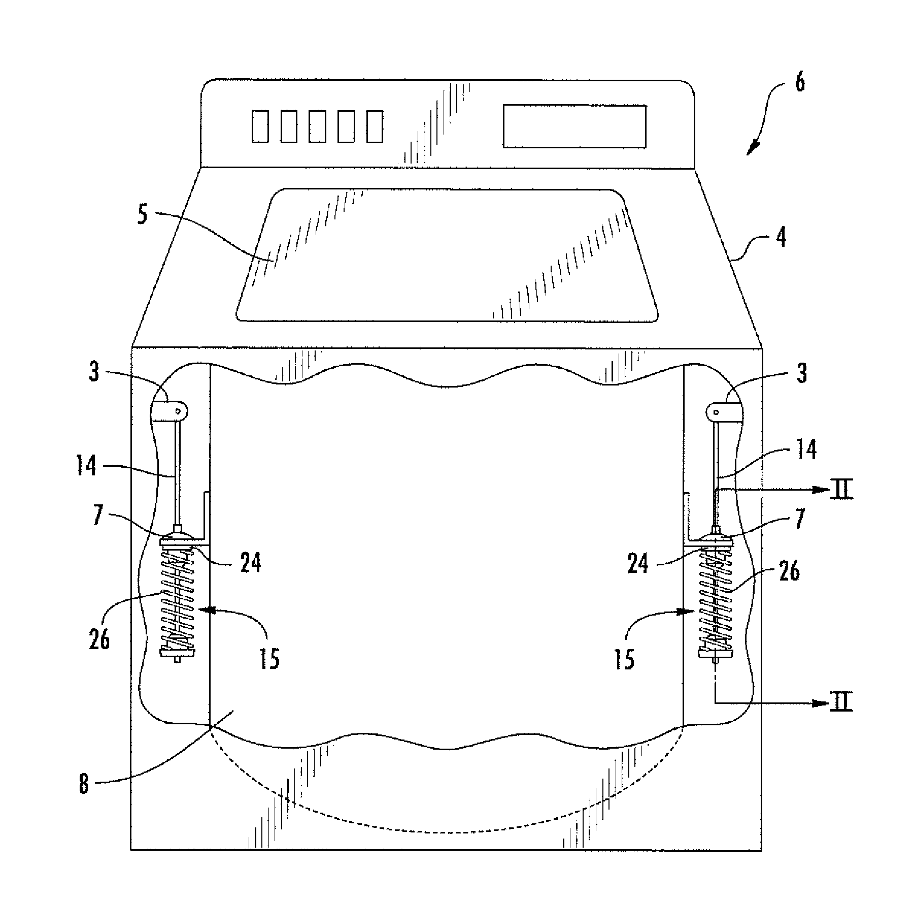
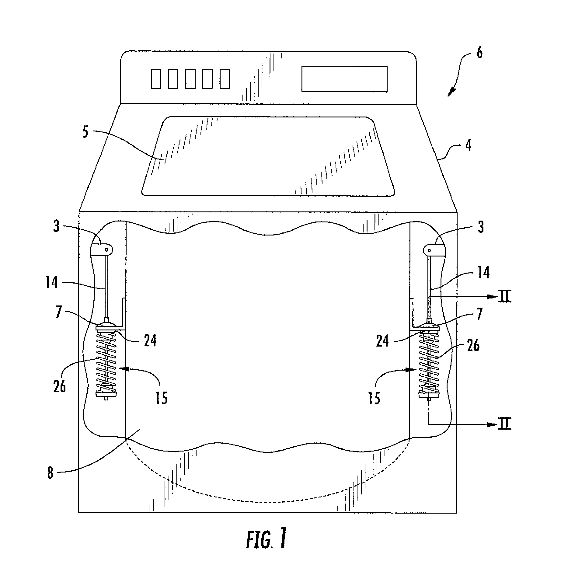
[0036]Referring initially to FIG. 1, there is shown a washing machine 6, which includes a cabinet and frame 4 and a drum 8 for receiving clothes to be laundered through a hinged cover 5. Drum 8 rotates and agitates the clothes during wash and spin dry cycles and is subject to vibrations during normal operation of the machine, particularly when there are unbalanced loads. Drum 8 is supported by a plurality of dampers 15 (two shown in FIG. 1) at various locations. The dampers are mounted in a tension mode and movably held by a hemispherical bracket 7 secured to the drum 8. The hemispherical upper surface of the end cap 24 of damper 15 nests within the hemispherical socket of bracket 7 to allow the dampers 15, 20, or 40 (shown in FIGS. 2-7) to move with the movement of drum 8 with respect to cabinet frame 4. Each of the dampers includes a friction rod 14 extending therefrom with the upper end of rod 14 secured to the frame 4 of the machine by a bracket 3. Typically, four such dampers a...


PUM


Abstract

A damper includes a housing having a friction element receiving chamber for receiving a planar friction element, such as foam pads. The foam is injected with grease. Two rectangular greased foam pads are inserted into an open housing within a pad-receiving recess in the housing. A cap is then assembled onto the housing. The housing-foam-cap subassembly is next assembled onto a friction rod with a spring coaxially surrounding the friction rod, having one end abutting the housing and the other end abutting a base at the lower end of the friction rod.

Description

CROSS-REFERENCE TO RELATED APPLICATIONS[0001]This application claims priority under 35 U.S.C. § 119(e) and the benefit of U.S. Provisional Application No. 61 / 779,677 entitled NON-CYLINDRICAL DAMPING ELEMENT SUSPENSION, filed on Mar. 13, 2013, by Tyler S. Hernden et al., the entire disclosure of which is incorporated herein by reference.BACKGROUND OF THE INVENTION[0002]The present invention relates to a damper that contains one or more non-cylindrical friction damping elements engaging the outside surface of a friction rod element.[0003]Dampers are employed in a variety of applications for preventing excessive, uncontrolled movement. In one application, for example, in horizontal or vertical axis washing machines, designed dampers are employed to prevent the washer basket from over-vibration during a spin cycle. U.S. Publication No. 2003 / 0183994 entitled DAMPER SPRING STRUT discloses the environment of such an application for a damper. U.S. Pat. No. 7,549,519 discloses another damper...

Claims


Application Information

Patent Timeline
Patent Type & Authority Applications(United States)
IPC IPC(8): D06F37/24F16F7/08F16F13/00
CPCD06F37/24F16F13/005F16F7/08D06F37/20
Inventor HERNDEN, TYLER S.VANDER ZANDEN, JAMES L.ATWATER, D. STUART
Owner SUSPA
Why Eureka
Try Eureka