
Vehicle transmission

a technology for transmission and motor vehicles, applied in mechanical equipment, transportation and packaging, gearing, etc., can solve the problems of limited installation space available in motor vehicles for transmission, and the weight of motor vehicles is to be increased only little or not, so as to reduce the cost and construction effort

Inactive Publication Date: 2016-01-28
ZF FRIEDRICHSHAFEN AG
View PDF4 Cites 4 Cited by
  • Summary
  • Abstract
  • Description
  • Claims
  • Application Information

AI Technical Summary

Benefits of technology

The invention is a vehicle transmission that can be used in both internal combustion engines and hybrids. It has multiple planetary gear sets that can be connected to two input shafts, which can be connected to the drive machines through disconnecting clutches or brakes. This design allows for a compact and high-gear transmission that can function with relatively few gear levels. The use of two input shafts can also enable a double-clutch transmission with two independent power paths, making it possible to implement a power-shiftable sequential gear sequence. Additionally, the invention allows for a shiftable coupling of the two power paths to expand the transmission ratio and drive possibilities. The number of gears in the main transmission can be doubled by adding a range group that can be shifted without interrupting tractive power. The range selector is designed with a lower gear step and minimal speed loss to minimize the tractive power interruption. Overall, the invention provides a compact, high-gear transmission that can be used in both hybrid and internal combustion engines.

Problems solved by technology

In addition, the installation space available in motor vehicles for the transmission is limited and its weight is to be increased only little or not at all in spite of the increased number of gears.

Method used


Image

  • Vehicle transmission
  • Vehicle transmission
  • Vehicle transmission

Examples


Embodiment Construction

[0098]As a preliminary remark it should be noted that, for simplification, functionally identical components are marked with the same reference numerals in the figures.

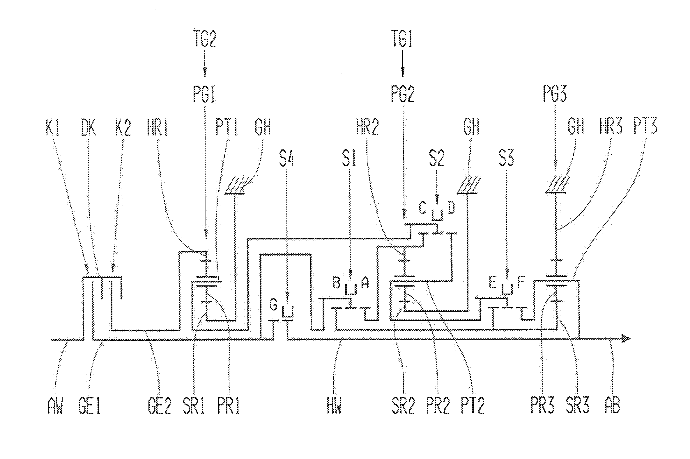
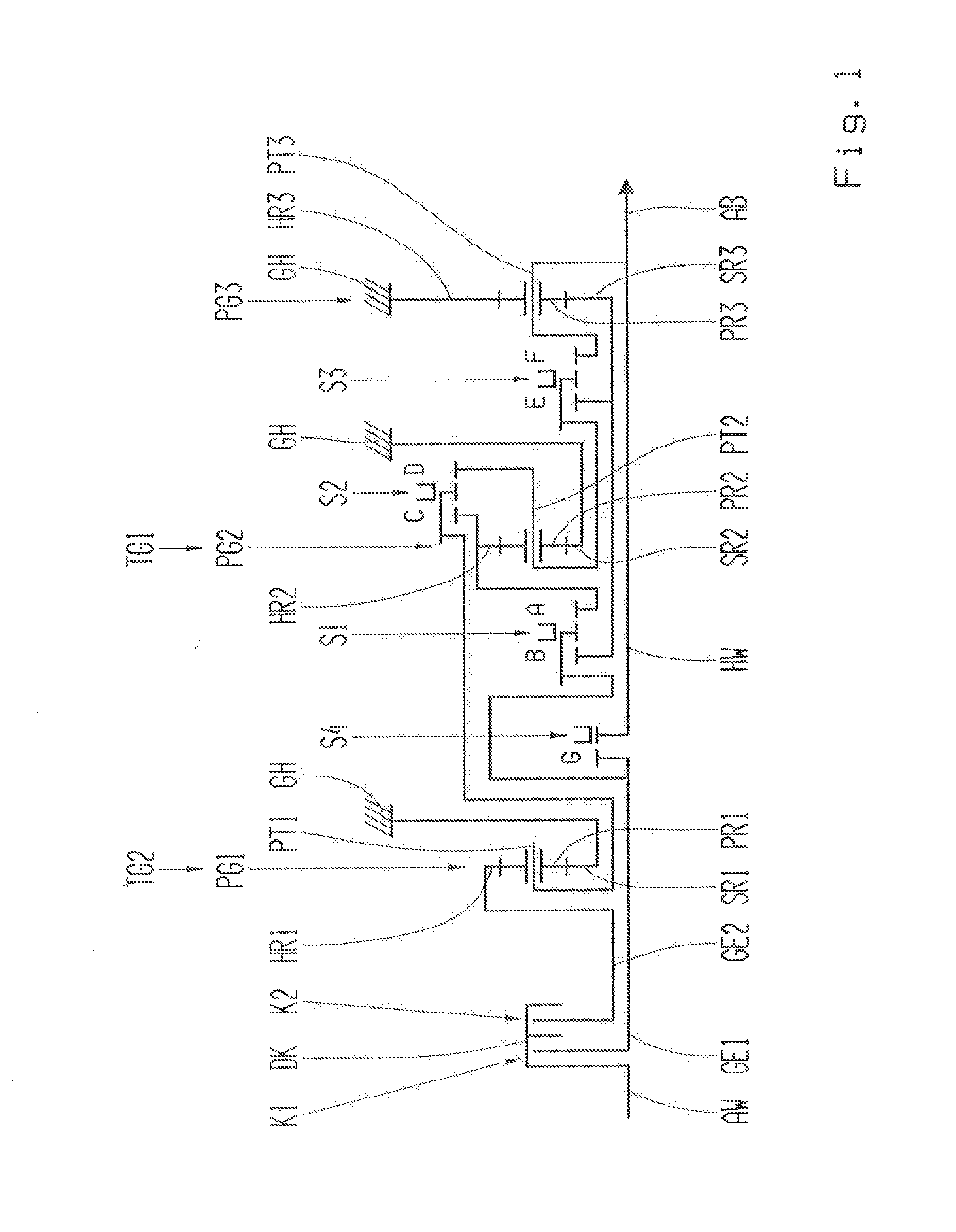
[0099]Accordingly, a vehicle transmission schematically illustrated in FIG. 1 essentially shows three planetary gear sets PG1, PG2, PG3, one drive shaft AW, two transmission input shafts GE1, GE2, a main shaft HW and an output shaft AB, coaxially arranged to one another.

[0100]The planetary gear sets PG1, PG2, PG3 are designed as simple minus gear sets, each comprising a radially outer ring gear HR1, HR2, HR3, an inner sun gear SR1, SR2, SR3 and a planetary carrier PT1, PT2, PT3, wherein the planetary carrier PT1, PT2, PT3 features a plurality of planetary wheels PR1, PR2, PR3 that mesh with the sun gear SR1, SR2, SR3 and the ring gear HR1, HR2, HR3.

[0101]The vehicle transmission according to FIG. 1 features a double clutch DK with two friction clutches K1, K2, the input sides of which are formed by a common clutch bas...


PUM


Abstract

A vehicle transmission having first and second transmission input shafts (GE1, GE2) and having at least three planetary gear sets (PG1, PG2, PG3). A sub-transmission (TG1, TG2) is allocated to each of first and second transmission input shafts (GE1, GE2) and one of first and second sub-transmissions (TG1, TG2) comprises at least the first planetary gear set (PG1), and the other of first and second sub-transmissions (TG1, TG2) comprises at least the second planetary gear set (PG2). To ensure that the vehicle transmission is economically manufactured and useful for both conventional and hybrid drive trains, a provision is that the transmission input shafts (GE1, GE2) be effectively connected or effectively connectable with the planetary gear sets (PG1, PG2, PG3), that it be possible to variably activate first and second sub-transmissions (TG1, TG2) for implementing multiple gears, and that one of the gears be shiftable as a direct-drive gear.

Description

[0001]This application is a National Stage completion of PCT / EP2014 / 052683 filed Feb. 12, 2014, which claims priority from German patent application serial no. 10 2013 204 172.1 filed Mar. 12, 2013.FIELD OF THE INVENTION[0002]The invention relates to a vehicle transmission.BACKGROUND OF THE INVENTION[0003]Increasing demands on the power and the fuel consumption of vehicles have resulted in a larger number of gears in the transmissions, both for passenger automobiles and also for utility vehicles. In addition, the installation space available in motor vehicles for the transmission is limited and its weight is to be increased only little or not at all in spite of the increased number of gears. In addition, transmissions are required which enable gear shifting without interruption of traction force and are usable with relatively little expenditure in various drive concepts.[0004]Vehicle transmissions having two input shafts are known, in particular double-clutch transmissions. In these...

Claims


Application Information

Patent Timeline
IPC IPC(8): F16H3/66F16H3/00
CPCF16H3/66F16H2200/2094F16H2003/445F16H2200/006F16H2200/0078F16H2200/0095F16H2200/0086F16H2200/201F16H2200/2012F16H2200/2015F16H2200/2097F16H2200/2053F16H2200/2058F16H2200/2056F16H2200/2061F16H3/006F16H2003/442
Inventor KALTENBACH, JOHANNESZIEMER, PETERBORNTRAGER, KAI
Owner ZF FRIEDRICHSHAFEN AG
Learn More