Worm biasing structure
- Summary
- Abstract
- Description
- Claims
- Application Information
AI Technical Summary
Benefits of technology
Problems solved by technology
Method used
Image

Examples
first embodiment
[0038]A first embodiment of the present invention will be described with reference to FIGS. 1 to 7B.
Configuration of Motor-Driven Power Steering Apparatus
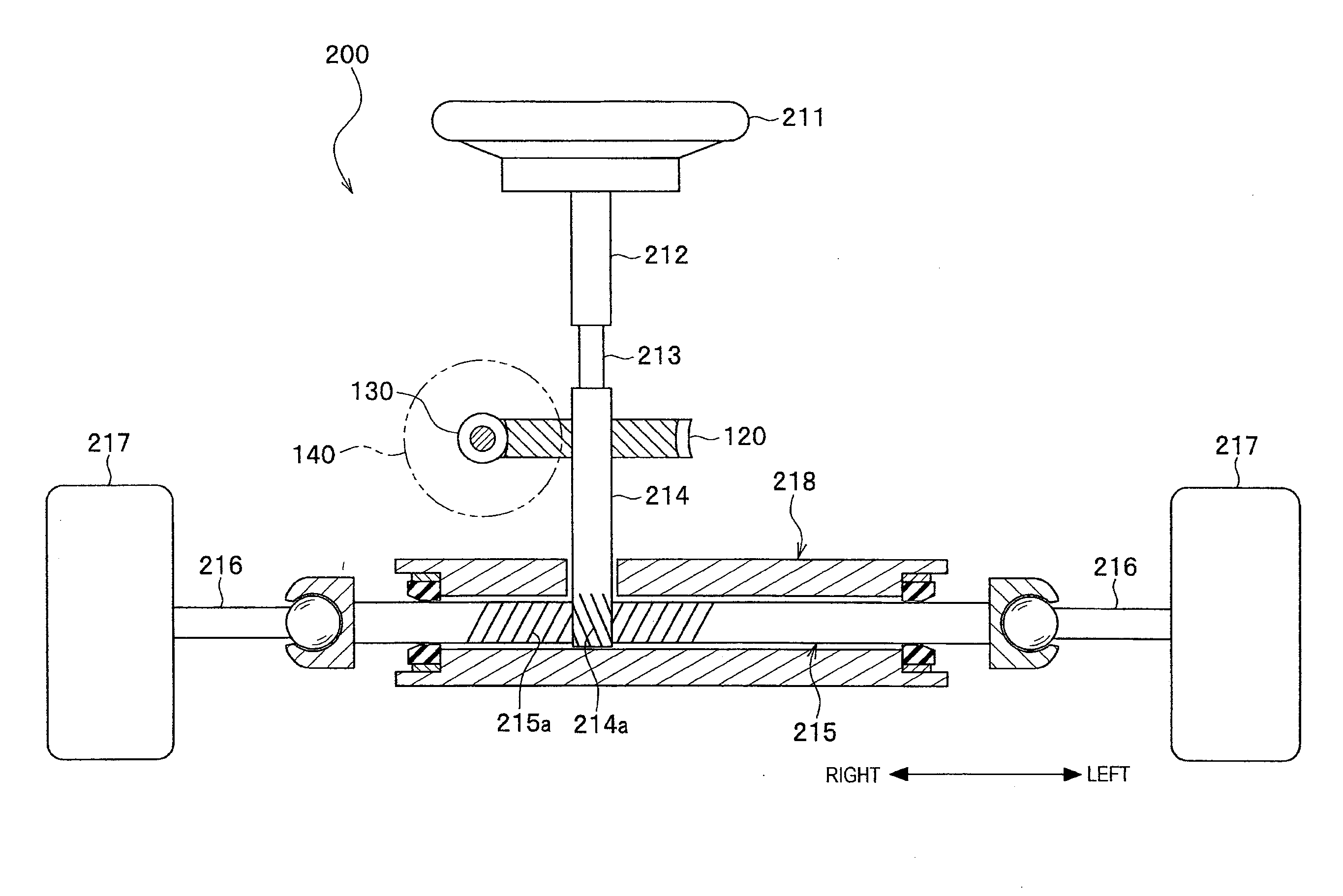
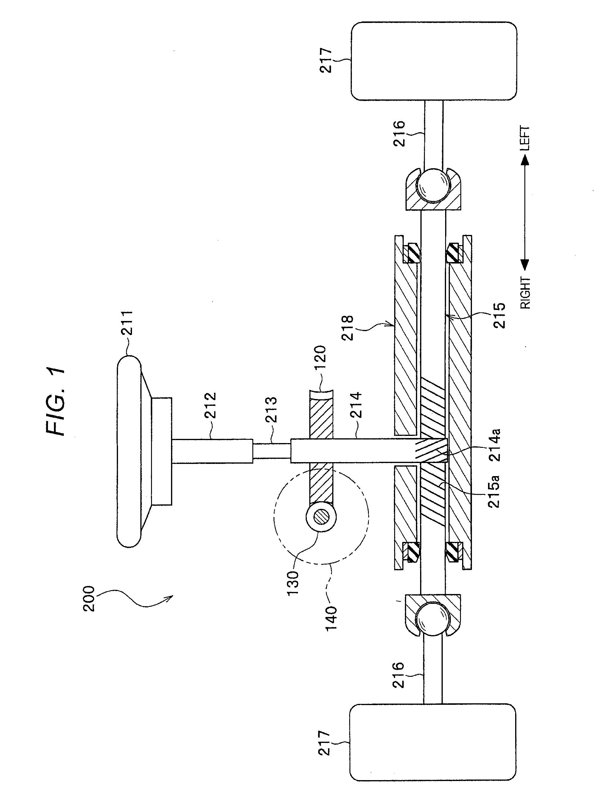
[0039]A motor-driven power steering apparatus 200 is a pinion assistance steering apparatus that inputs an assistance force to a pinion shaft 214. The motor-driven power steering apparatus 200 may be a column assistance steering apparatus or a rack assistance steering apparatus.
[0040]The motor-driven power steering apparatus 200 includes a steering wheel 211 operated by a driver; a steering shaft 212 that rotates integrally with the steering wheel 211; a torsion bar 213 connected to a lower end of the steering shaft 212; the pinion shaft 214 connected to a lower end of the torsion bar 213; and a rack shaft 215 that extends in a width direction (lateral direction) of the vehicle (direction from left to right or right to left shown in FIG. 1).
[0041]Pinion teeth 214a of the pinion shaft 214 mesh with rack teeth 215a of the rack shaft ...
modification example
[0077]The embodiment of the present invention has been described above, but the present invention is not limited to the embodiment, for example, the following modification can be made.
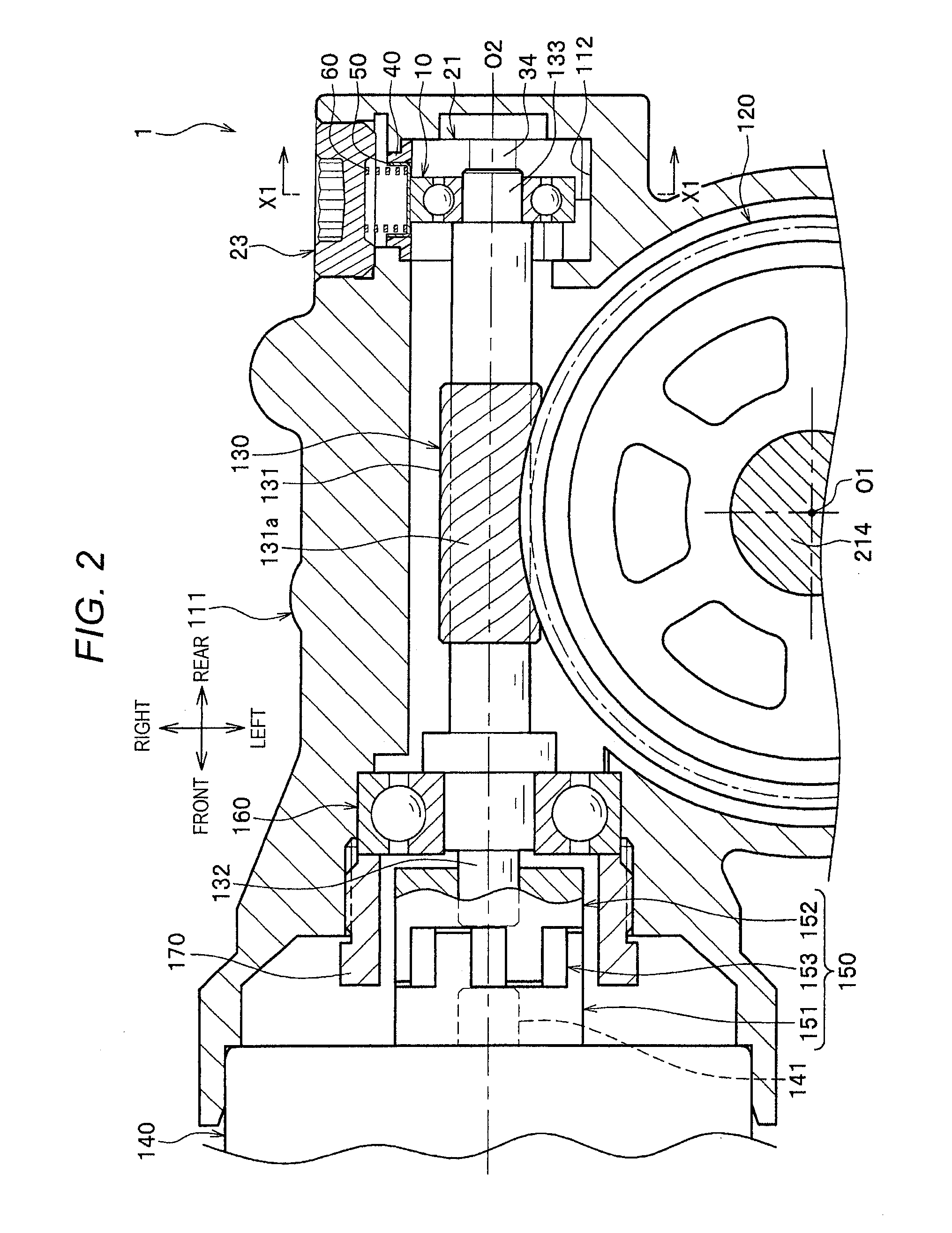
[0078]In the configuration of the embodiment, the distance W34 between the pair of guide surfaces 34, 34 is smaller than the outer diameter D10 of the second bearing 10 (W3410), but, for example, the distance W34 may be set to be equal to the outer diameter D10 (W34=D10).
[0079]In the configuration of the embodiment, the respective outsides of the guide surfaces 34 of the holder main body 30 are thinned, and the D-shaped gaps S are formed between the outer surfaces 35 and the housing hole 112 (the inner circumferential surface 113 (refer to FIG. 6)). However, for example, the housing holes 112 on the respective radial outsides of the guide surfaces 34 are partially recessed outwards in the radial direction, and thus gaps may be formed between the respective circular arc-shaped outer surfaces (parts of t...
second embodiment
[0080]A second embodiment of the present invention will be described with reference to FIGS. 8A and 8B. The descriptions of points different from the first embodiment will be given.
[0081]A plurality of ribs 71 is formed on the respective radially outer sides of the guide portions 33 of a bearing holder 22 according to the second embodiment, and extends in the longitudinal direction (axial direction of the second bearing 10) (direction from front to rear or rear to front shown in FIG. 8A). The plurality of ribs 71 is disposed at substantially equal intervals in the lateral direction (direction from left to right or right to left shown in FIGS. 8A and 8B). A radially outer end (vertically outer end) of each of the ribs 71 is in contact with the inner circumferential surface 113 of the housing hole 112.
[0082]A groove (thinned portion) 72 is formed between the ribs 71, 71 adjacent to each other in the lateral direction, and extends in the longitudinal direction (axial direction of the s...
PUM
 Abstract
Description
Claims
Application Information
 - R&D
- Intellectual Property
- Life Sciences
- Materials
- Tech Scout
- Unparalleled Data Quality
- Higher Quality Content
- 60% Fewer Hallucinations
Browse by: Latest US Patents, China's latest patents, Technical Efficacy Thesaurus, Application Domain, Technology Topic, Popular Technical Reports.
© 2025 PatSnap. All rights reserved.Legal|Privacy policy|Modern Slavery Act Transparency Statement|Sitemap|About US| Contact US: help@patsnap.com